
|
|
| Elliott Sound Products | Project 264 |
 Main Index
Projects Index |
| Foreword | Introduction | Problem Of Gain | Log Hoax | Analysis | Prototypes | Measurements | Conclusions | References |
This article is reproduced from material submitted by Pascal, and a minimum of text editing was performed to maintain the original intent of the submission. All graphs have been updated, and schematics changed to match the ESP standard style. There have been a few minor changes that were necessary to keep the intent but remove direct reference to me. Additions by the editor are in square braces and italics, and tagged with a small ESP logo ( ). Note that all formulae have been re-done to allow easy representation in HTML, so they look different from those submitted. All have been checked for accuracy, but errors may still be present. All images provided by Pascal have been 'branded' with the ESP logo to allow easy identification if (when) they are stolen by one of the many unscrupulous 'webmasters' who never produce anything of their own, but steal the work of others.
The curve shown next indicates that at 50% rotation, the output level is 0.1, which is -20dB. In the Baxandall article referenced by Pascal, this is exactly what one should aim for to get a satisfactory gain response over the full range of the pot. Ideally, one would set the system gain so that the audio level (SPL) in the listening area is at a comfortable level with the pot at 50% rotation. If one were to use a linear pot, the level would only be 6dB down at 50% rotation!
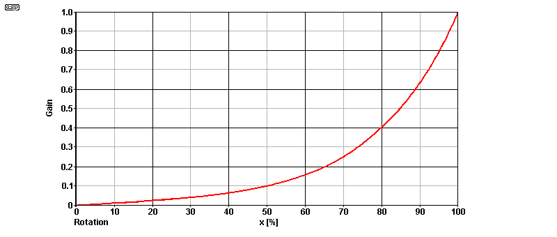
As Pascal mentions further below, the term 'log' is at best a misnomer, and at worst a hoax. A so-called 'log' pot is actually exponential (the opposite of logarithmic). The term is (one suspects) intended to convey the auditory response, which is logarithmic. It's very doubtful that anyone will start calling log pots 'exponential' any time soon, but the term 'audio taper' is actually a better description, and that's fairly common. Compare the response shown above with that in Fig. 4, and it's a pretty good match to the orange curve (B = 10). Note that rotation [x] is electrical (about 270°) and not mechanical (typically 300°).
At the beginning of this work, I wanted to limit my analysis to Baxandall's active volume control. But along the way, I thought it would also be interesting to compare it with other so-called "logarithmic" volume control methods, as shown in Project 01 "Better Volume Control".
As you will see at the end of the document, I propose a double potentiometer solution, and since it is not commercially available, I propose a simple method to make it using two stereo potentiometer currently available.
The Baxandall active volume control is a quasi linear-in-dB volume control that can replace that which is usually implemented in audio amplifiers by means of (roughly) "logarithmic" potentiometers.
The basic schematic can be found in the book of Douglas Self 'Small Signal Audio Design' on pages 231 to 238, the practical circuit depicted below being on page 237 (except the values of R2 and R3), as well as in ESP's above-mentioned article.
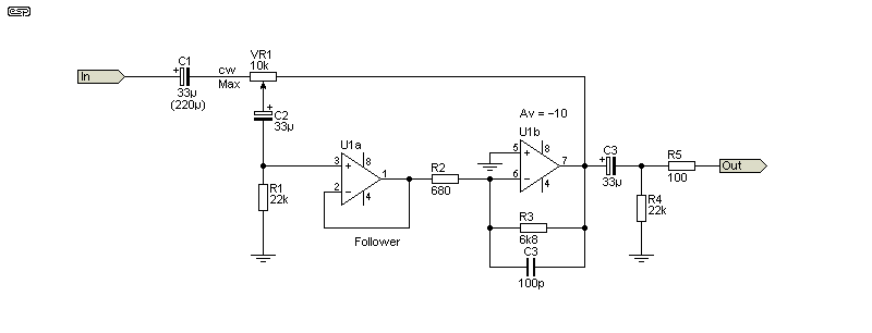
The gain G with respect to the position of the wiper 0 < x < 1 is given by:
(1) G = VOut / VIn = x / (( 1 - x ) +1/B)
(2) Where B = R3 / R2 (i.e. The gain of the inverting opamp stage - 10 as shown in Fig 1)
Note that because G is negative, the minus sign in equation (1) must be removed before conversion to dB. The gain F at the output of the follower is simply the gain G divided by -B :
(3) F = x / ( 1 - B ( x - 1 ))
The maximum of the gain G for x = 1 is equal to B. In dB or log scale we get the following curves for different values of B, and it is obvious that the shapes of the curves change.
It's interesting to note that B affects G mostly at full volume. This is why it's more pertinent to look at F, as we will see in the next paragraph.
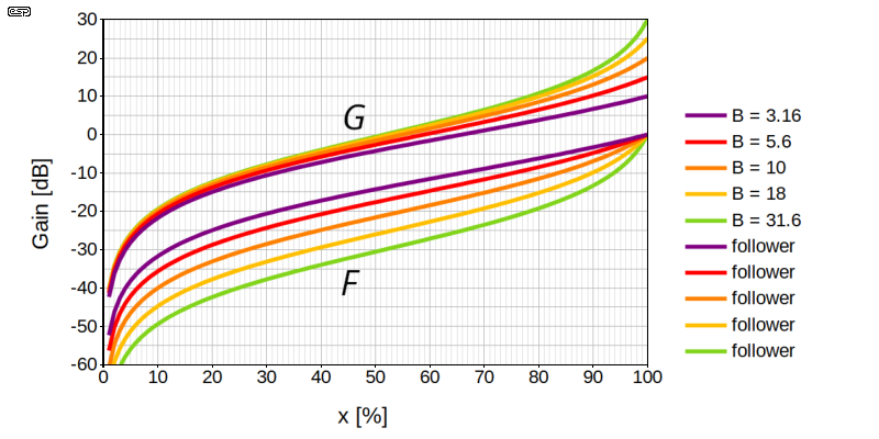
You will understand here that I invented nothing. I just suggest the usage of the circuit from an other point of view. As Rod mentioned after Figure 3 in the article "A Better Volume Control", the gain of 20 dB at maximum volume control is far too much for many preamps. It's suggested to reduce the gain of the second opamp, but that affects the shape of the curve as we see on the graph above. The simple and obvious way to solve this problem, which nobody seems to see, including me until recently, is to use the output of the follower, as shown in the reordered schematics below.
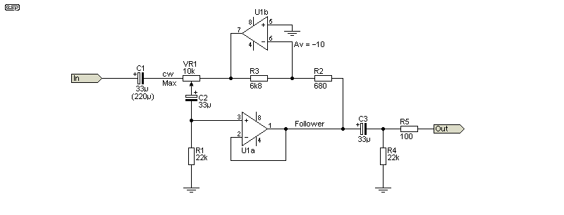
If for example you add a follower at the input VIn of the circuit, with a 10K input resistor you have a direct replacement for a 10K pot with no modification of the gain chain and a constant input impedance. Note that since the output of U1b must not saturate, this constrains the maximum allowable voltage at the input VIn of the circuit.
[Note: The 100pF cap (in parallel with R3 (in Fig. 1) must not be included in this version. The reduction of high-frequency gain causes high-frequency boost at the output of the follower, because the voltage at the 0% position (fully anticlockwise) of VR1 will have high-frequency rolloff. This makes it frequency dependent. ]
What is the origin of the misuse of the term "logarithmic" to describe the potentiometers used to control the volume of amplifiers? Just take the curves of Fig. 2 for the case of the follower in a linear scale.
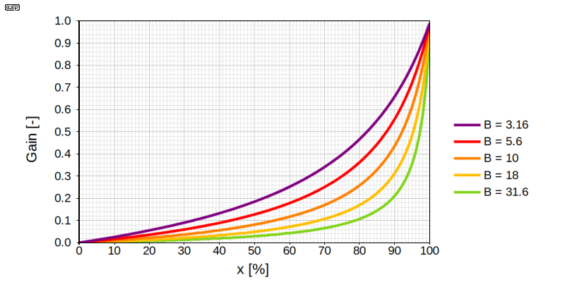
These curves are and must be of the exponential type with an increasingly steep slope to compensate for the logarithmic compression of human hearing.
I asked the following question to Google AI:
Why are volume potentiometers for audio amplifiers described as logarithmic when in reality they have an exponential characteristic to compensate for the logarithmic compression of hearing?
The answer is multiple, but they agree with my position. As an introduction they said:
The term "logarithmic potentiometer" describes the relationship between the mechanical position and the perceived volume, not the mathematical curve of the electrical resistance.
Here is the breakdown of why this naming convention is used: (blah blah blah)... [Follows a list of arguments.]
In the list, they mention the approximation of a linear potentiometer loaded by a resistor, as in the Project 01 article. However, I didn't wait for this answer to do my own analysis. I even went further than that.
[ I performed a couple of queries via AI (Claude and ChatGPT) and got similar responses. A so-called 'log' pot should ideally be exponential, but common commercial offerings use piecewise linear tracks (often only two) to get a (very) rough approximation of an exponential characteristic. We perceive volume/ loudness on the basis that a 10dB increase equates to the sound being 'twice as loud', but sound pressure level (SPL) has increased 100 times! Note that this applies to pure tones, and music is usually perceived differently. ]
Starting from the Project 01 article with respect to the above title, I wanted to see how the curve is changing with respect to the ratio P/R of the potentiometer and resistor resistances.

After a few calculations, the transfer function is given by:
(4) Vout / Vin = x / ( 1 + ( x - x^2 ) P / R )
To summarise The P01 article, the linear-in-dB gain range is approximately 25 dB at the center. The main problem lies at lower levels, where the variation is far too rapid for high-power amplifiers. This is also the case for Baxandall, but its gain is about 20 dB lower.
The level of -20 dB is attained at x = 55 % for Baxandall versus x = 24% for P/R (look at the orange curves which are optimal to my opinion).
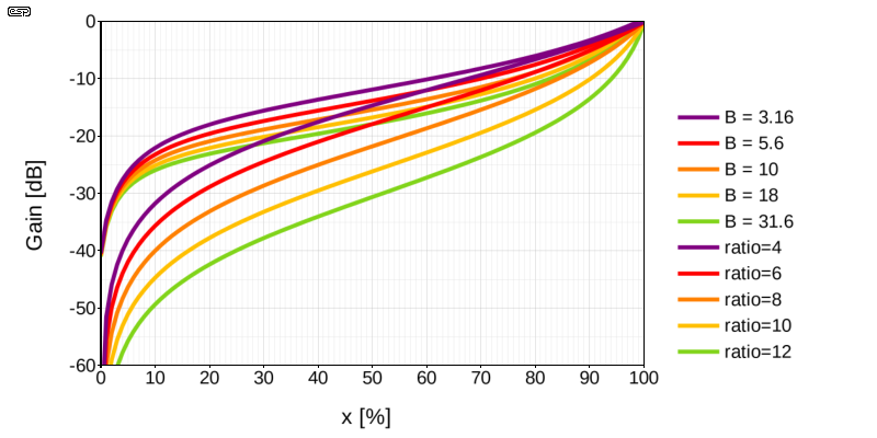
In the ESP article it's said that we cannot find quad potentiometers, but I will show you later that it is quite easy to build one with two dual potentiometers. Moreover we have the liberty to choose two different values, as for the potentiometer loaded with a resistor.

The transfer function is the same than that of equation 4, multiplied by x:
(5) Vout / Vin = x² / ( 1 + ( x - x² ) P1 / P2 ))
And it changes a lot the result!
Most of the potentiometers are available in the pseudo-series E3 (1-2-5). The next figure shows the results obtained for ratio = P1 / P2 = [ 1, 2, 5, 10, 20 ].
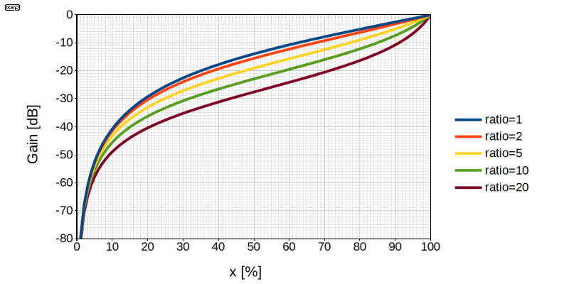
As we will see later, the ratio of 10 is the closest to the Baxandall with the gain of -10.
I did not ask the question to Google AI because I do not want to give them free good ideas ...
I found the service manual for my good old Technics SUV470 amplifier. (Mouse-over the image to see the full-size version.)
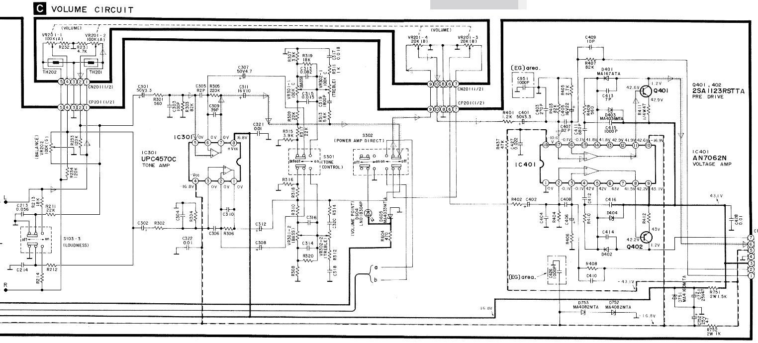 Figure 9 - Part Of The Schematics Showing The Volume Control Of The Technics SU470 Amplifier |
Here's a fair-quality close-up of the volume control circuit from the service manual. As you can see, it has two cascaded potentiometers, separated by the tone control circuit, which includes an amplifier which is kept in the path when the tone control is disabled. The first potentiometer is a 100kΩ (A) with a 4.7kΩ resistor at its lower end. After the the amplifier/tone control there is a 20kΩ pot (B).
Therefore the second potentiometer does not load the first one. From this point of view, this is not similar to my proposition.
I also found the service manual of the Technics SU-VX800. The volume control is basically the same than that of the SUV470, with some more stuff around the second potentiometer. So nothing new under the sun ...
The cascaded potentiometers you mention in your article, found in a guitar amplifier have the same values. From this point of view, this is not similar to my proposition.
The cascaded potentiometers you mention in your article, found in a guitar amplifier have the same values. From this point of view, this is not similar to my proposition. I imagine that in the 1980s, all Japanese hi-fi manufacturers developed various ideas for volume control. But for the last 20 years, everything has been done with digital signal processors (DSPs). Conclusion: all potential patents are in the public domain. In any case, you can copy a pending patent as long as it's for your own use and without generating profit.As far as I'm concerned, I've never found any mention of this approach using two linked potentiometers of different values. And I think if you had found it, it would already be included in your article.
In the following graph I compare a 100kΩ/12kΩ P/R (as in your article), a 100kΩ/10kΩ P1/P2 and a Baxandall with a gain of 10.
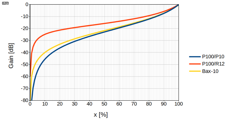
To check the two approaches in real conditions, both with measurements and listenings, a Baxandall and a dual potentiometer prototypes have been constructed.
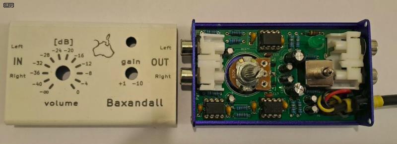
This prototype was made a long time ago, but a bad surprise was noticed during the test. After investigations, it turned out that I had mounted a S-shaped potentiometer from AliExpress. Since I destroyed a bit the PCB when removing the faulty potentiometer, I had to build a new one.
The most commonly used potentiometers are those of the WH148 series. An interesting feature is the opening at the rear which allows access to the drive shaft via a hexagonal hole, as illustrated in the photo below.
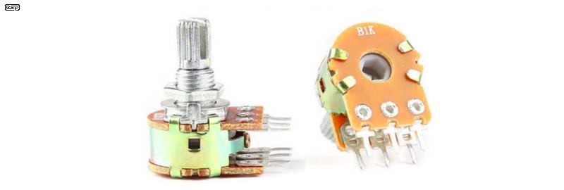
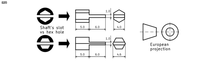
You need to choose the model with the grooved shaft and a slot, as shown on the image. Note that the orientation of the slot relative to the hexagonal hole may depend on the manufacturer, as shown in the following figure.
Everyone has a bunch of 4mm Z-shaped Allen keys that come with all IKEA furniture. Choose the ones that are hexagonal along their entire length and select the softest ones. Then, grab a file and a saw and get to work.
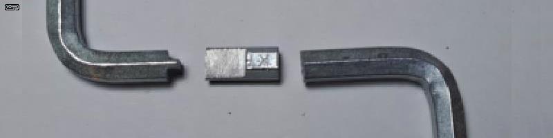
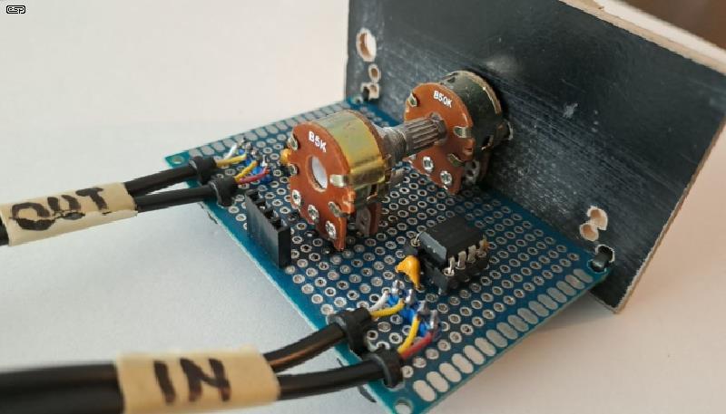
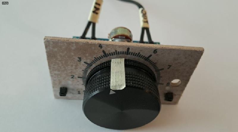
The connector in the back of the prototype is for the power cable. I used a couple of available linear potentiometers, i.e 50kΩ/ 5kΩ for P1/ P2. I added followers at both inputs and outputs.
Because the Baxandall prototype is capacitively coupled, I made both measurements with the same setup. I simply used sinewave generator with 1 VRMS at 100 Hz and measured the output voltages with an AC voltmeter.
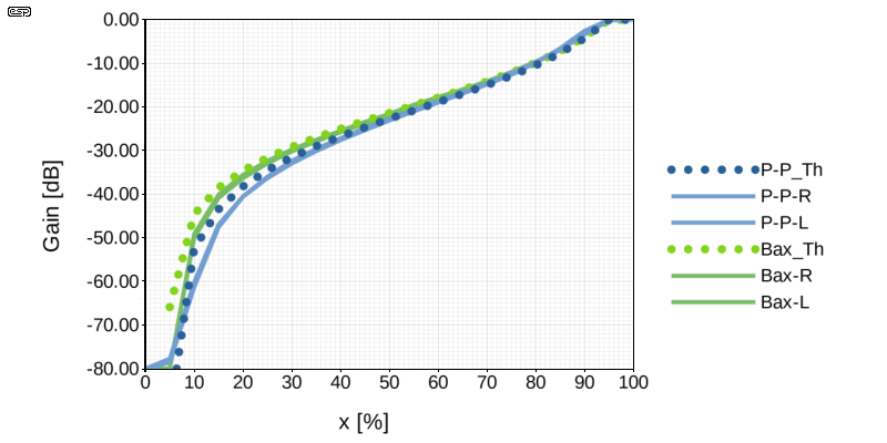
According to the measurements, a slight difference is observed in the lower values. Note that the theoretical curves were fitted within the linearity range of the potentiometers, that is, between 5% and 95% of their travel (the low-resistance path at the end covers about 5% of the track). For both prototypes, there is a small (certainly negligible) difference between the left and right channels. I haven't selected the best matched potentiometers, but those with a more meticulous approach can do so.
There is a fairly minor difference between the two implementations. The dual potentiometer is slightly less aggressive at the lower end of the adjustment range, making it better suited for high-power amplifiers. That is the sole reason I prefer this solution. However, the dual potentiometer requires input and output buffers; in terms of components, the two solutions are therefore roughly equivalent.
Google search : 'baxandall active volume control'
I found this document from Texas Instruments: Active Volume Control for Professional Audio (https://www.ti.com/lit/pdf/TIDU034) in which they use the Baxandall volume control with a gain of -1. I didn't put this gain in my analysis, because I think that, as they say "Ideal gain characteristic: -20dB over full potentiometer rotation" is far from ideal. Anyway, they never mention using the output of the follower.
Here is a representative from Altium using the Baxandall volume control in its standard configuration: (https://resources.altium.com/p/baxandall-volume-control-audio).
I also found this file: Wireless-World-1980-11-S-OCR.pdf (https://www.worldradiohistory.com/UK/Wireless-World/80s/Wireless-World-1980-11-S-OCR.pdf)The document mentioned above contains a detailed article by Peter Baxandall titled "Audio Gain Controls" in which he presents a circuit (Figure 25) for reducing the gain. Clearly, even he himself did not think of using the follower output ...
I will stop the search there. In any case, I am almost certain that no one else came up with the idea of the linked dual potentiometer!
Project 01 - A Better Volume Control - ESP website.
| Main Index
Projects Index
|