
|
| Elliott Sound Products | Project 263 |
 Main Index Projects Index |
| Introduction | Initial Tests | Description | Further Tests | Final Design | Power Supply | Conclusions | References |
While it might seem that the topic of transformers has been done to death, there are many more things we can learn and experiment with. Not everyone loves transformers, but they remain the best possible solution for complete galvanic isolation between an audio source and destination. Most balanced connections now use active balancing circuitry, but that doesn't provide galvanic isolation. Just what is galvanic isolation? The term simply means that there's no electrical connection between the two pieces of equipment, and therefore a ground loop (aka earth loop) cannot exist.
If there's no electrical connection (an ohmmeter will show an open-circuit), circulating current (the ground loop) cannot be created. Fibre optics also achieve galvanic isolation, but they require an ADC (analogue to digital converter) and a DAC (digital to analogue converter), with the setup generally configured for S/PDIF (Sony/Philips Digital Interface). Some equipment comes with this already, but if it doesn't, it has to be added. You also need a fibre-optic interconnect to transport the signal. None of this is hard or particularly expensive, although adding one or more S/PDIF interfaces may cost you more than you'd like to pay.
I've described a method to drive a transformer using negative impedance, both in the article Negative Impedance - What It Is, What It Does, And How It Can Be Useful and in Project 228 - Negative Impedance Test Amplifier. However, while tinkering with something else, another idea came to mind, which was (more-or-less) promptly examined. The article Transformers - The Basics (Part 1) (along with subsequent articles on the topic) provides some useful insight into transformer operation, and one part in particular is easy to implement.
The optimum source impedance for any transformer is very low (or even negative), so adding series resistance never works well. I (briefly) considered negative impedance for this project, but it actually gives rise to 'unintended consequences'. In particular, leakage inductance becomes a bigger problem than is otherwise the case, and that can cause high frequency rolloff at a much lower frequency than you'd hope for. While you'll often see claims that audio transformers are used for impedance matching, that's true in only a few cases. It was certainly the case with 'pots' (plain old telephone system) phones and infrastructure, but they had cable lengths that were measured in tens (or even hundreds) of kilometres. For audio systems, there is almost no requirement for impedance matching, except for valve (vacuum tube) power amplifiers, where the plate resistance of the output valves must be matched to the speaker load.
Most audio interconnections use a (very) low impedance source, and a comparatively high impedance for loads. This is commonly known as a 'bridging' load, and several loads can be connected to a single source without interactions. This is not changed just because a transformer is included in the circuit. Many transformers do specify a 'termination', which is often a Zobel network - a resistor and capacitor in series. This improves the squarewave response and prevents any unintended high frequency boost.
The project described here is definitely one for experimenters. Don't expect to find further info elsewhere - I've tried and found bugger-all. The technique is known to (some) people using current transformers, but they are a completely different application. It looks very much like no-one else has thought of using a transimpedance amp at the secondary of an audio transformer. Not too many years ago it wasn't really practical because of the difficulty (and expense) of providing a separate isolated power supply. This limitation no longer exists.
Strictly speaking, a transimpedance amp is a current to voltage converter, and it expects a true current source as its input. A transformer certainly provides current, but it's not a true current source because it has a very low resistance. This is circumvented by using a capacitive input for the transimpedance amp, so the DC resistance is effectively infinite (well, very high anyway - infinity is a tad difficult in the real world).
The difference between using a negative impedance converter (NIC) and the technique described here is that the NIC is intended to allow more drive current into the transformer, allowing it to operate at a higher level. With the 'new' technique described, the transformer is operated at a (comparatively) low voltage, with the level restored by an opamp line driver at the secondary side. Coupled with the reduction of saturation distortion because of the (effectively) short-circuited secondary, you can drive a transformer isolated balanced line at anything up to +20dBu (7.75V RMS) if you wanted to go that far. Around +10dBu (2.45V RMS, or +7.78dBV) will usually be more than enough.
However (there's always a 'however'), there is a 'contra-indication' (there's usually one of those too). Normally, leakage inductance isn't a major problem, because its reactance is small compared to the transformer's resistive component (primary and secondary). It eventually causes some rolloff in 'normal' use, but when the load impedance is close to zero, even a small leakage inductance becomes significant. This causes the high frequency response to be rolled off sooner than would otherwise be the case. Just 1mH of leakage inductance has a reactance of 6.3Ω at 1kHz, and 63Ω at 10kHz. This is not an insurmountable problem though, especially if it means you can use a $20 transformer instead of one costing $100 or more.
Any audio transformer will have a load at the 'far' end - the equipment being supplied with a signal. It doesn't matter if this is a multi-channel mixer or another piece of a hi-fi setup. For mixers, an input impedance of around 2.2kΩ is fairly typical. Some may be a bit higher, but less is uncommon. Home audio gear usually has an input impedance of around 22k, but it can vary from 10k to 100k. In most cases, a 600Ω transformer will be used (particularly with 'pro audio' gear), as these are probably the most common.
It's important to understand that transformers do not have an 'intrinsic' impedance. They are wound to provide sufficient inductance for the lowest frequency of interest when used at their design impedance. A 'high impedance' transformer simply has more inductance than a 'low impedance' transformer, but either can be used at any impedance you like. If you use a 10kΩ transformer at 600Ω it will work fine, but you may see high frequency rolloff earlier than expected because of leakage inductance. Reverse the situation (600Ω used in a 10kΩ system) and it doesn't have enough inductance to pass low frequencies, and the core will saturate well before it should.
The inductance needed depends on the nominal impedance and the lowest frequency of interest. At a minimum, a '600Ω' transformer should have an inductance of at least 4.8H to get down to 20Hz, but neither of those I tested come anywhere near that. Getting the necessary inductance also depends on the way the transformer will be driven. It's rare (and not a good idea) to drive any transformer with its design impedance, although this is normal with valve amplifier output transformers (the primary impedance is determined by the plate/ anode resistance suggested in the datasheet). Normally we should aim to drive transformers with the lowest practical impedance (which can be negative!).
Like almost everything, there's a need to compromise. Transformer manufacturers make compromises to ensure that the product meets specifications, without going beyond what's expected. To do so would add cost to the transformer, and most 'professional' audio transformers are already quite expensive. It's not uncommon to see them costing upwards of $100-$300 ... each (two are needed for stereo). For the application described here, I recommend a 600Ω 1:1 transformer, selected for low leakage inductance (if the maker deigns to tell you this). It should always be part of the specification, but it's often omitted.
Unfortunately, most small (low cost) transformers use a ferrite core. Ferrite has a very sharp transition to saturation, so ferrite transformers tend to transition into saturation quite abruptly. This makes the operating level fairly critical, and if the maximum is reached, the abrupt arrival of (low-frequency) distortion is very noticeable. Some ferrites may also show distortion at high frequencies. This can be well above the distortion of an otherwise similar transformer using nickel-steel or permalloy (a particularly good core material).
There is one other option for galvanic isolation - a linear optocoupler that uses a single LED and two photodiodes. One photodiode is used for feedback, and the other for the output. An example is the IL300. The claims are impressive, but expecting distortion much below 0.5% is probably unrealistic. They do have a wide frequency response, from DC up to 100kHz, but use comparatively high impedances, so noise is likely to be a real problem. I have looked at these, but to be honest I was unimpressed.
Before starting, I tested the two transformers (described below) with 'conventional' voltage drive (low impedance), at 40Hz and 50Hz. A comparison was also done between a more-or-less normal load resistance (3.9k) and a zero-ohm load. The latter includes an opamp (with gain), so output voltages are much higher than normal. For the resistive load test I used an output voltage of 1V, which is a little higher than the transformers are designed for. The 'zero ohm load' was the input of a 'virtual earth' transconductance amplifier.
Many cheap transformers do not provide any indication of which winding is the primary. The easy way to tell (in most cases) is to measure the DC resistance. The primary is almost always wound onto the former first, and for a 1:1 transformer, it will have a slightly lower resistance because less wire is needed to provide the number of turns needed. In some cases, the secondary will have a few extra turns to minimise the insertion loss. A 1:1 transformer is never really 1:1, because the winding resistance causes some voltage loss when the secondary is loaded with the design impedance (e.g. 600Ω). Any loss of signal level is called insertion loss.
The first test was on a $2 eBay transformer. THD at 50Hz was 2.25%, rising to 3.6% at 40Hz. The telecomms (telecommunications - analogue phone system) transformer gave 1.4% THD at 50Hz and 2.5% at 40Hz. When used with a zero ohm load, the output voltage (at the output of the current to voltage [transimpedance] circuit) was 2.32V (RMS), and THD was 0.72% at 50Hz, rising to 0.95% at 40Hz. the distortion is lower if these trannies are operated at lower levels, but low frequency rolloff is still significant.
The second transformer was tested the same way, with the same input voltage (1V). THD measured 1.4% at 50Hz and 2.5% at 40Hz. With a zero ohm load (plus transimpedance amp), the output voltage was 5.2V, and THD measured 0.25% at 50Hz, rising to 0.4% at 40Hz. The output voltage was greater because the winding resistance of the telecomms transformer is roughly half that of the $2 transformer.
The transformer details are shown in Table 1. For these initial tests, I used a ±12V supply for the secondary side, but it will be lower than that if the suggested power supply is used. These tests were intended to provide a 'base-line' so that subsequent results could be compared to the results obtained driving the transformers conventionally (from a near zero ohm source).
As discussed in some detail in the transformer articles, the reason that transformers distort is due to core saturation. As the frequency is reduced and/ or the amplitude is increased, the core will saturate, eventually causing gross distortion. We already know that saturation is at its worst with no load, and while a few people may dispute this, it remains true regardless. If the secondary of the transformer is shorted, we can keep saturation at bay (as it were), allowing higher input levels at lower frequencies. Naturally, the impedance presented by the primary (to the drive amplifier) is much lower than normal, but this isn't insurmountable.
Unfortunately, a transformer with a shorted output doesn't provide any voltage. However, it does provide current, so we can use a transimpedance amplifier - a current to voltage converter. The basic idea of a transimpedance amp is shown below, and it's simply an opamp stage with a current driven into the inverting input. Due to my 'two rules of opamps (Rule 1)' (see Designing With Opamps - Part I), the voltage at the two inputs should be the same, and since the positive input is earthed, the inverting input should provide a 'virtual earth'. This is a common circuit in mixing consoles, where the virtual earth/ ground mixer stage is the most common. With an 'ideal' transformer, the voltage across the primary will be (close to) zero, but ideal transformers aren't available from any manufacturer.
As a result, there will be a voltage across the primary that's directly related to the winding resistance. If the transformer has a winding resistance of 100Ω, the voltage at the terminals will be determined by the drive current. That may require some additional series resistance, because opamps don't like trying to drive close to a short circuit. Normally, we try to drive transformers from the lowest impedance possible (including a negative impedance/ resistance), and that doesn't change when the output is effectively shorted. We can get the best of both worlds by including a limiting resistance within the feedback loop. You need to be beware of opamp clipping though, as it can happen even with a relatively low output level.
The opamp driving the transformer should have a 'sensible' series resistance to ensure that the opamp doesn't 'see' a very low resistance, and if we use an NE5532 or LM4562 that can be around 600Ω (560Ω is a standard value). To ensure a low drive impedance, the resistor is within the feedback loop. Equalisation could be provided with a small capacitor in parallel with the resistor, but that only works if the series resistor is outside the opamp's feedback loop, which is not recommended. Using transformers intended for more than 600Ω means that leakage inductance increases, making the need for EQ essential. You might just get away with no EQ if the leakage inductance is less than 1mH, but only if the winding resistance is reasonably high.
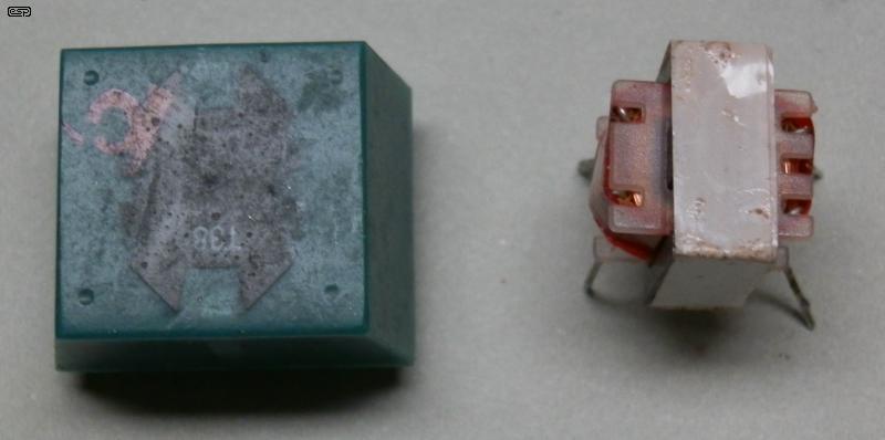
The test transformers are shown above. On the left is a 600Ω 'telecomms' transformer, designed for telecommunications (analogue telephone) interfaces. The other is the AU$2.00 'eBay' transformer, which is much smaller and cheaper. Transformers similar to the one on the left typically cost around AU$30 or more. The eBay transformer is probably one of the most basic you'll ever come across. No specifications are available, but the inductance is lower than it should be and the maximum input level is very limited. The core is only 14.5 x 12 x 5mm, which is tiny.
| Transformer Type | RPri | RSec | Cp-s | LPri | LLeak |
| 600 Ω Telecomms | 57Ω | 69Ω | 17 pF | 2.7H @ 100Hz | 984µH @ 10kHz |
| $2.00 eBay 600 Ω | 131Ω | 136Ω | 3.0 nF | 965mH @ 100Hz | 1.14mH @ 10kHz |
The high frequency response in the circuit shown here is determined by the leakage inductance (LLeak). This is usually small compared to the total inductance, and its reactance normally doesn't cause any problems. This changes when the output is effectively short-circuited. If we use the 984µH figure for the telecomms transformer, the output will be 3dB down at just over 20kHz. This is determined by the following, assuming 126Ω total winding resistance ...
f = RSeries / ( 2π × L )
Where RSeries is the total winding resistance, plus any external resistance.
f = 126 / ( 2π × 965µ ) = 20.8kHz
For the $2 transformer, the -3dB frequency is over 37kHz, and it can be used without EQ. There will be a small loss (about 1.2dB) at 20kHz.
The output doesn't require any boost if you can handle a drop of about 3dB at 20kHz (the rolloff is 6dB/ Octave). Most people will consider this to be inadequate, and it's very audible. The solution is a simple boost circuit around the drive opamp. This is easily implemented, and the details are shown in the next section. I've also included the primary to secondary capacitance, as that has an influence at high frequencies.
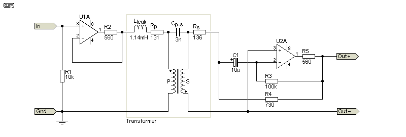
This circuit is conceptual, because the details depend on the transformer. To avoid an impossibly low feedback resistance for the opamp stages, they have a 560Ω resistor before the feedback network. The 'concept' circuit was wired up on my opamp test board, which uses very ordinary 1458 opamps (roughly the equivalent of a dual 741). With the very low load impedance across the output of U1 I expected the opamp to complain bitterly, but it did no such thing. The input level was fairly low (about 560mV), and with the values shown that provided an output level of just over 2V RMS. At this voltage, the opamp wasn't upset by the low-value feedback resistor. In case you're wondering about the use of a 730Ω resistor, I had two (1k and 2.7k) that I swapped back and forth, and eventually used in parallel.
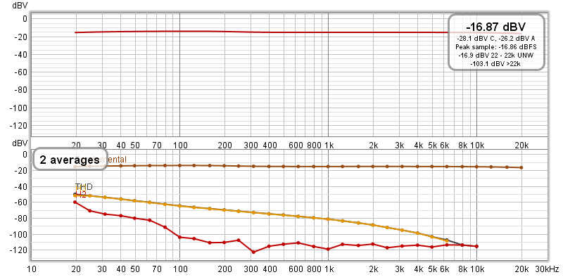
The trace was obtained using the $2 eBay transformer and the Project 232 Distortion Measurement System, and distortion at 20Hz is -50dB with a reference level of -12dB. Distortion at 20Hz is 0.12%, and it falls steadily as frequency increases. At 100Hz it's down to 0.0023%, and it continues to fall as the frequency goes up. The orange trace is the 3rd harmonic, which is dominant with transformers with no DC in the windings.
Remember that this is a $2.00 transformer, which has no right to be anywhere near that good in any respect. The output level from the virtual earth opamp was 522mV RMS for this test. At an output of 2V RMS (+6dBV), the measured distortion at 20Hz was still below 1.5%. Consider that a transformer costing almost AU$40.00 at the time of writing (Element14 #1689035) has 3% THD at 20Hz at 0dBm (775mV) when loaded with 560Ω.
While you might hope that the eBay transformer (which is supposedly designed for audio) might be the better of the two, the telecomms transformer is superior. Both show significant rolloff below 100Hz, and when driven conventionally, the eBay transformer has a rather disturbing 15% harmonic distortion at 30Hz, with a rather measly 560mV output (down from 1V at 'mid frequency'). The output was rather horribly distorted due to saturation. With a transimpedance amp using an NE5532 opamp in my opamp test board (Project 41) things improved markedly.
Using a NIC can reduce distortion dramatically, but the output level is still limited. The use of a transimpedance amplifier means that the output level is controlled by the feedback resistor and the available supply voltage, so only the input level is of interest. I used 1V RMS from a (close enough to) 0Ω source (an opamp), and with an output voltage of 2.56V RMS the input was about 590mV. Distortion at 20Hz was less than 3%, falling to 1.5% with a 1V output (295mV input). This isn't spectacular, but listening to the output (harmonics only) there wasn't much to hear, and it was a 'clean' signal at 60Hz - the 3rd harmonic.
The necessary EQ requires two extra resistors and a capacitor. Unfortunately, there's no easy way to calculate the EQ network, so some experimentation will be needed. As a starting point, if we know that the output needs an extra 3dB of gain at 20kHz, the opamp must provide at least 6dB of gain at that frequency. In reality, we need to arrange for a little more gain (around 8dB), with the frequency set by a capacitor. This is achieved (close enough) with the following circuit. The transformer used this time is the telecomms version.
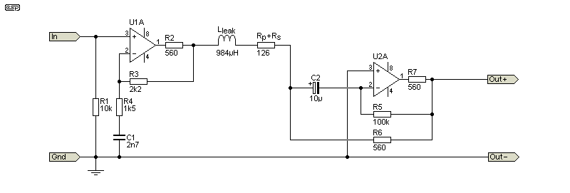
The EQ is based on U1, using R3 and R4 to set the maximum gain, and C1 determines the frequency where boost starts. The network shown increase the upper -3dB frequency from 19kHz to over 50kHz. The response at 20kHz is -3.3dB without the EQ, and -0.07dB with EQ. There's a small (0.12dB) boost at 12kHz due to the EQ circuit. If you calculate the 3dB frequency of R4 and C1, it's just under 40kHz.
Providing equalisation to prevent premature rolloff caused by the leakage inductance isn't difficult to do, but it requires both accurate measurements and some calculations. However, a transformer with low leakage inductance will most likely be fine with no EQ at all. The $2.00 eBay transformer has 1.14mH leakage, and it's passably flat from 20Hz to 20kHz without any EQ. It's 'better' than the telecomms transformer because it has higher resistance windings, so Lleak is less intrusive. The response at 20kHz is -1.3dB which will be fine for most applications. If you wanted to add EQ, R4 would be 3.9k and C1 is 1nF. This gives response to 20kHz with only 0.2dB loss.
Normally, the primary and secondary circuits would use separate (and isolated) power supplies, so the secondary side has no (local) connection to ground. This wasn't used for my initial tests, and the circuit itself doesn't care one way or another. Normally, the secondary side is grounded at the remote end only. This is true galvanic isolation, but with active circuitry. The output would also normally be a dual opamp, with +ve and -ve outputs in antiphase. This doubles the output level without affecting the transformer. The output is balanced whether you use an inverted stage or not, because it's floating (not ground referenced).
The telecomms transformer was better, and for initial tests I tested at 40Hz which is a bit more realistic. With an output of 0dBV (1V) and an input of ≈125mV, the distortion was below 0.2%. In all cases, the input current was limited by the internal impedance of my function generator. For a 1V output, the input current was only 1mA RMS, easily provided by any opamp. Needless to say, the transformer output current was almost the same, and the transimpedance amp has an output of 1V/ mA. This can also be written as 1mA/ V, a transconductance of 1mS (1 milli-siemens).
A very important side-effect of using the transformer this way is that low-frequency amplitude performance is greatly improved. You'd expect a small transformer (either of those I tested) to roll off rather badly below 100Hz, and this was the case with 'normal' voltage output. Once the transimpedance amp was added to the mix, both transformers were almost dead flat to 20Hz! This is equivalent to (or better than) the performance gain you get with a NIC, without the possibility of instability.
Predictably though, there are a couple of down-sides, one of which it's a killer - or it would be without the tricks described in Project 233. By using a DC-DC converter with galvanic isolation, you can power the transimpedance amp easily. You now have a fully isolated audio path, and it takes almost nothing to provide a galvanically isolated, fully balanced audio signal that can be used in any situation where ground loops cause intractable hum problems. You can do it with low-cost parts too, so there's no requirement to pay $hundreds for really good transformers.
The other down-side is that leakage inductance becomes a problem if it's more than a few hundred microhenries. The $2 transformer was fine with only 143µH, but 1.7mH (the 'telecomms' transformer) proved to be too high. It's easily fixed with EQ, but it's easier if EQ isn't needed. A 1.7mH inductance has an impedance of 214Ω at 20kHz. At low frequencies, the gain of the transconductance amplifier is 8.34 (due entirely to the winding resistances). At 20kHz, that falls to roughly half, a loss of 6.5dB. This is easily corrected with modest equalisation. You may have expected more attenuation, but there's a phase difference that has to be considered.
Much as I'd like to support the manufacturers of good audio transformers (and there aren't that many left), it's hard to justify spending a vast sum on transformers, particularly if you only wish to experiment. Consider that even fairly expensive models (at around AU$40 each) will still have up to 3% distortion at 20Hz, and will probably be at -3dB at 25Hz or so (depending on the inductance). The majority have just enough inductance to be usable, but to get good performance at 20Hz means an inductance of at least 4H is needed for a 600Ω transformer.
By using the transimpedance amp, this is no longer a limitation, and response can be flat to 20Hz without needing extremely high inductance. As noted above though, leakage inductance may become an issue due to the very low impedance. It can be equalised, but that will involve some experimentation. Much as I'd like to be able to provide a simple formula, it's not feasible. If you use a simulator you can adapt the general principle shown in Fig. 2, or use it as a starting point for bench tests.
Many tests were also run using a simulator with a ferrite transformer core. With the output open-circuit, there was 3.5% distortion of the input current with no load, and that fell to 0.1% THD with the transimpedance amplifier connected. This relationship held over a range of frequencies and amplitudes, demonstrating that the process is repeatable both on the workbench or a simulator. In general, you can expect the transimpedance amp to be at least the equal of a NIC, but with greater control over the output level. With a NIC, the transformer still has to pass the full desired output voltage, but a transimpedance amp makes the output level adjustable if necessary, while maintaining a voltage at the transformer's primary low enough to avoid saturation at any sensible frequency.
Should you choose to use a much better transformer, then the results are even more impressive. Distortion (for the same output voltage) is typically improved by an order of magnitude, even at 10Hz you can get a good signal with little distortion. It's somewhat disconcerting when a transformer's distortion measurement is dominated by that of the signal generator or sound card, as I also used Project 232, a PC based distortion measurement system to see the harmonic structure.
Note that the techniques described are for transformers rated for 600Ω or thereabouts. Using higher impedance transformers (with correspondingly higher inductance) means that the leakage inductance will also be higher. It's fairly common to find the leakage inductance to be around 1/1,000th of the primary inductance. It's possible to get less, but usually only by using bifilar windings which increase the capacitance between primary and secondary. This reduces the allowable common-mode withstand voltage, but the technique described is not intended to be used to provide full (i.e. high-voltage) isolation - it's intended to eliminate earth loops, and nothing more. A 'typical' earth loop will generally have a voltage of perhaps a few hundred millivolts or so.
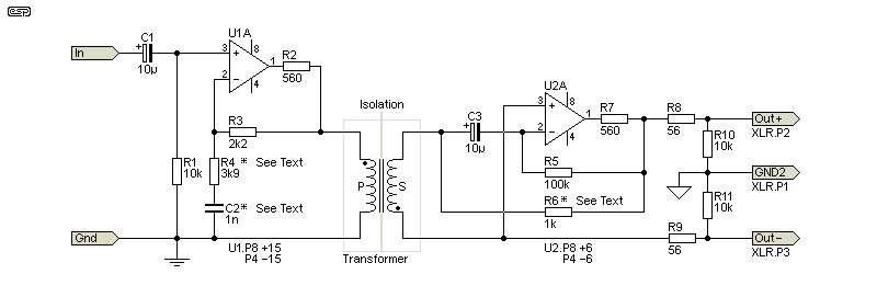
The values for R4 and C2 depend on the amount of EQ needed for the transformer you use. As shown, they are correct for the $2 transformer. The value of R6 is adjusted to get the desired output voltage. Aiming for around 2.5V is a reasonable output level for professional gear, but you may need to reduce it for home/ consumer products. The maximum input voltage should not be more than 1V, and around 500mV means that you will be well clear of any audible distortion. The opamp must be designed to be able to provide normal output into a 600Ω load, so you could use NE5532, OPA2134 or LM4562 types. Any opamp that can operate with a 600Ω load will most likely be quite alright.
Note that the transformer's polarity is reversed so the input and output polarities are the same. While there's no requirement for 'absolute' polarity (a positive input results in a positive output), it's generally considered a good idea, and it's expected in professional installations. It's a convention that's been in use for a long time, and it's so easy to get it right that it would be silly to have an inverted output.
The XLR pinouts shown are the standard for a balanced line. Optionally, Pin 1 (earth/ ground) can be connected to +Out and -Out by resistors R10 and R11 (around 10k). These serve to provide an artificial mid-point for the output. Some degree of RF protection can be obtained by connecting capacitors in parallel with R10 and R11. These will work with R8 and R9 to establish a high-frequency rolloff. If used, around 10nF is suggested. These will provide a -3dB frequency of about 280kHz. You can use more capacitance if you wish, but it's not necessary.
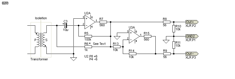
The differential output stage means you need to add another opamp, but it can provide a higher output level. In theory you can get up to 5V RMS output (+14dBV) into a 'typical' 10k load. I can't think of a good reason to need that much, but the option exists. The extra opamp is another inverter, and the transformer's polarity is unchanged. Although not strictly necessary, a 560Ω resistor (R15) is included in the feedback loop to maintain the best possible balance between the two outputs.
If you only need isolation of unbalanced-in to unbalanced-out, the following circuit is used. It's much the same as the basic version shown in Fig. 5, but there's no requirement for the two balancing resistors, and the output 'stopper' resistor is increased to 100Ω. This is the most useful version for providing galvanic isolation for home systems.
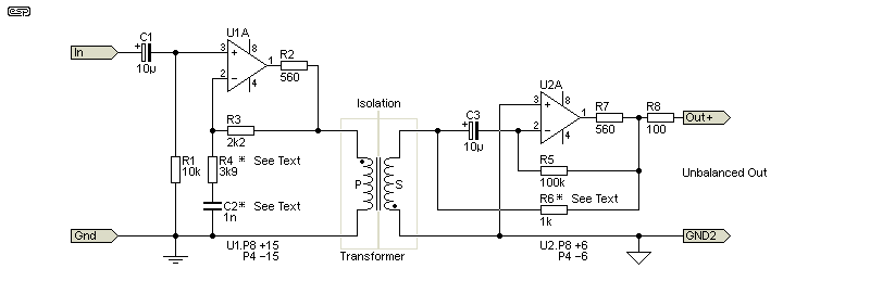
It's probable that for normal home usage this is all you'll need. You may need to reduce the value of the feedback resistor (R6) to maintain unity gain. The value should be the same as the sum of the winding resistances, so around 270Ω if you use an eBay $2 transformer. It's best if you measure the winding resistance, as I'd expect that different batches of these low-cost transformers will have different characteristics.
There are two options for the power supply, with a B1212 (or similar) 1W DC-DC converter module being the most cost effective. However, you can use a traditional linear supply as well if you prefer, and the transformer provides the isolation. The secondary supply must not be grounded to the main supply's ground point, as that would defeat the purpose of using the transformer.
The suggested supply for the secondary side is a simple ±6V supply, obtained from a 12V DC-DC converter. If you use a dual opamp to obtain a floating electronically balanced output (but still with full galvanic isolation), you can get an output level of up to 5V RMS (+14dBV) driving a 1k load. There's no need for anything greater than this in any normal installation.
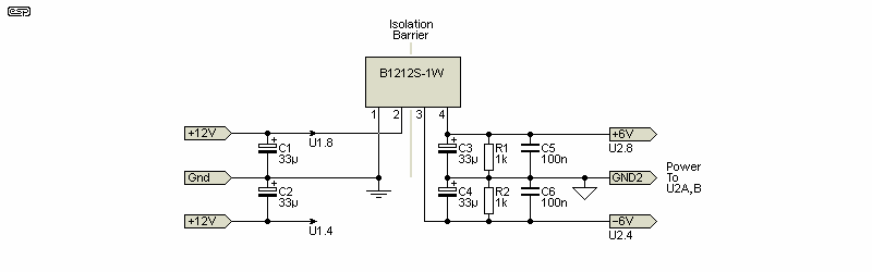
The power supply for U2 must be isolated from the main supplies, and the circuit shown in Fig. 8 is an example. This follows on from Project 233, which describes a number of ways to obtain a low-power isolated supply. The B1212-1W (1W output, so 83mA for the 12V version) is readily available from many suppliers, with some costing less than AU$4.00 each. Predictably, these are Chinese versions of those made by Mornsun, Murata, Recom, Traco and CUI, but my tests have shown no significant differences.
One disadvantage of the DC-DC converters is that the only common input voltages are 5V and 12V, so the 'local' side (i.e. that to the left of the transformer) needs a ±12V supply rather than the more common ±15V. You can use a separate +12V supply for the converter, but that's a bit of a nuisance. Almost all standard audio circuits will function perfectly with a ±12V supply.
There's also the option of using a linear supply, using P05-Mini (for example) and a small mains transformer (1 or 2VA will be enough). The secondary side of the interface uses a single opamp, so it will draw a maximum of 10mA or so. Even if you choose to use the differential output amplifier, the current will be less than 20mA. Yet another option is a 12V plug-pack (aka wall wart) supply, as these are always Class-II (double-insulated). Before you decide on a cheap unit from eBay, see Dangerous Or Safe? - Plug-Packs (aka 'Wall Warts') Examined.
The fact that no-one (or so it seems) has thought of this for transformer coupling is a little baffling. It's almost as if designers in the power industry (where current transformers are common) and those in the audio industry never talk to each other. In reality, this is probably true. Unlike audio, the power industry isn't rife with snake-oil vendors and believers in 'magic' components. Very few 'audio people' will have much to discuss with their counterparts in industrial or commercial power fields. I have worked in both areas, and even though I haven't designed an industrial switchboard for over 45 years, regular readers will be aware that my coverage of power applications is more comprehensive that you'll find on other 'audio' sites.
Being able to get good performance from cheap parts is always rather satisfying. There will always be some limitation with cheap parts, and there are some that can't be dealt with, such as inter-winding capacitance. Whether or not this causes issues in any given application depends on the nature of the ground loop noise to be mitigated. Mostly you're dealing only with mains hum, but there can be exceptions. While the circuits have been both simulated and bench tested, it's not feasible to cover every possibility. Be especially careful to ensure that there can never be more than a few volts of common mode (ground loop) noise. Most audio transformers are not designed to handle anything over ≈50V or so, as the insulation isn't designed for any more.
Unfortunately, none of the cheap transformers you can buy (including 'budget' options from major suppliers) include an electrostatic shield between the windings. These are often necessary if there is high frequency common mode noise (e.g. from switchmode power supplies). Using transformers designed for telecommunications applications can also work well, and these are easily identified by the claimed frequency response being from 200Hz to 3.5kHz. Most have fairly low winding resistances and they will require equalisation.
It's probable that most people won't bother trying the ideas described here unless there's a serious cost constraint for the project. All of my tests were performed using 1458 opamps (under AU$1.00), but the project is still cheap if you use NE5532 opamps. In most cases it's easier to use a decent transformer, but don't expect to get anything suitable for much less than AU$25 each. Using the 'trick' shown here you can build an entire stereo isolator for less than that.
There's no doubt that the idea presented is a little crazy, but that's not a reason to ignore it. Being able to get true hi-if performance from a cheap transformer means that otherwise intractable ground loop problems can be fixed quite cheaply. You don't need to spend a fortune for really good transformers, but you can get much the same performance from a couple of cheap transformers. If it doesn't work out for you, the loss is minimal - just the cost of a couple of budget transformers, a few passive parts and some IC sockets (if you use expensive opamps). The power supply isn't wasted either, because there's always a need for power supplies.
Predictably, there are no references, because no-one else seems to have thought of doing this. Despite several different search terms (and search engines), nothing was found. I do suggest that you read the following ESP articles ...
Negative Impedance What It Is, What It Does, And How It Can Be Useful
Project 228 - Negative Impedance Test Amplifier
| Main Index Projects Index |