
|
|
| Elliott Sound Products | Project 260 |
The accelerometer described in Project 181 is just as valid today as when it was published, but it lacks the ability to be calibrated (not especially important, but useful). There's also no inbuilt way to listen to the signal being detected. Seeing it on a scope is one thing, but being able to hear the signal is surprisingly useful. My reason for building this version was prompted by a machine that had a 'dicky' bearing, and a scope trace is useless for this - you must be able to listen to it to appreciate the peculiar noises that bearings and other mechanical contrivances can make when they are worn or just noisy.
The variable filter also lets you adjust the response for the task at hand. The ADXL335 is very noisy within the audible range, so if you don't need the high frequencies they can be filtered out. The default range is from around 650Hz to 3kHz (-3dB), but this is easily changed by using smaller or larger caps (C2 and C3). For the headphone amp, I decided to use P113 rather than a more common (and economical) LM386 or similar single-chip power amp, partly because I consider the LM386 to be rather awful, so I don't keep any around.
I used a ±15V linear supply based on the P05-Mini board, but a 24V switchmode supply would be alright at a pinch. It's not as though we are trying to get very low noise, because the accelerometer IC is noisy anyway, and any noise from an SMPS will be insignificant. The unit can be operated from a lower supply voltage, but that will make it very difficult to calibrate if you want to obtain the 1V/ g sensitivity I wanted. This is because you can easily run out of headroom, as the gain of the first stage is about 3.5 (but this will vary depending on each individual accelerometer). Does calibration matter? Not really, but there may be a time when you really do want to see how many gs (gravitation units) are being applied to the accelerometer board itself. Gravity at the earth's surface is unity.
Project 181 should be read along with this one, because it shows measured results from a variety of different tests. The explanations and scope captures show the kind of thing that can be measured or heard easily, and all were done using the ADXL335 accelerometer board. This is the only option shown here, but there are other accelerometers that can be used, including precision types if your application is critical. The unit described is not intended to be a precision device.
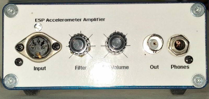
The above photo shows the front panel of my new unit. No, it's not especially glamorous, but it's functional and everything is easily accessed. I used a 3-pin DIN connector on this unit (the original used an XLR connector), but you can use any 3-pin connector you like. I never used to have a high opinion of DIN connectors, but I've mellowed over the years and I consider them to be tolerable - at least in the 3-pin version. As the pin count rises they become harder and more fiddly to wire.
The panel was printed on a standard laser printer, and was then laminated and cut to size. This is a quick and low-cost way to make panels for all manner of test gear (in particular), but the edges need to be protected (in this case by the blue plastic surround) to prevent them from coming apart. This is also why the panel is attached using washers - they protect the corners. I haven't included internal photos, as I expect every build will be different from mine, and the internal layout is not at all critical.
Most of the circuitry is quite straightforward, but there are parts that need clarification. The nominal sensitivity of the ADXL335 is 300mV/g, but this is somewhat variable. If you'd prefer a calibrated system, this is only appropriate for AC because it's too irksome to add a zeroing facility without extra complication. The two test points (TP1, TP2) shown in Fig. 1 can be bridged out to allow calibration, which is described fully further below. Normally, these test points are left open, so the circuit is AC coupled. The low-frequency -3dB point is well below 10Hz, so slow variations can still be detected easily.
The first stage has a typical gain of around two, but it needs to be adjustable if you want the 1V/g calibration I used. This is followed by a variable 12dB/ octave filter, so unwanted high frequencies can be removed, making the signal far less noisy. The filter has a gain of 1.67 (4.43dB) which is fixed to give the sub-Chebyshev filter characteristic I used. It has a very modest 0.04dB boost before rolloff, so it is so close to being Butterworth that it's a moot point. This type of filter is required here, because dual-gang pots always have 'equal' values. I put that in quotes because the tolerance of most pots is pretty poor (typically ±10% or worse), so the filter shape will change a little depending on the pot setting.
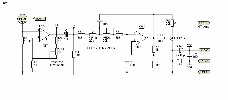
The first stage is DC coupled, and the nominal quiescent output from the ADXL335 is around 1.5V. The gain of U1a will increase that to ~3V with zero g, obtained by aligning the X-Axis parallel to the ground. The output voltage of U1a will vary from about 2.4V to 3.6V with 1g applied, assuming a gain of exactly two. This is at odds with the claimed output and gain, but the ADXL335 has an output impedance of about 32kΩ (±20%!), so the DC voltages are attenuated slightly because of R1 (about 1.9V across R1 at zero g). Actual accelerometer ICs will be a little different - mine had an output of 290mV/g, so needed a bit more gain. The measured voltage at the input of U1a were as follows ...
| g (Position) | Voltage | ΔV |
| 0 (horizontal) | 1.2431 V (Ideal 1.2365 V) | |
| +1 (base down) | 0.9907 V | 239.2 mV (245.8 mV) |
| -1 (base up) | 1.4823 V | 252.4 mV (245.8 mV) |
As is apparent from the table above, the output is not perfectly symmetrical. I was careful to align the sensor board horizontally for the reference measurement, but I freely admit that it may not have been as accurate as it could have been. That may or may not have been the cause of the error, but this is not intended as a precision measuring system. If the maximum and minimum are referred to the 'ideal' (averaged) centre voltage, the swing is symmetrical. These devices are surprisingly sensitive to a small angular error - well under 4° is easily detected, with the hard part keeping it steady for the duration of a measurement. The datasheet for the original Analog Devices (AD) IC says that the 0g quiescent voltage can vary from 1.35V to 1.65V, but be aware that the little modules you can buy do not use an genuine AD chip, but a Chinese (or perhaps Taiwanese) clone. The accuracy of these is a bit of an unknown. If the quiescent output voltage is exactly 1.5V from the IC, the input to U1a will be 1.136V due to the attenuation of the IC's internal resistor (nominally 32k) and the 100k input resistor (an attenuation of 1.32).
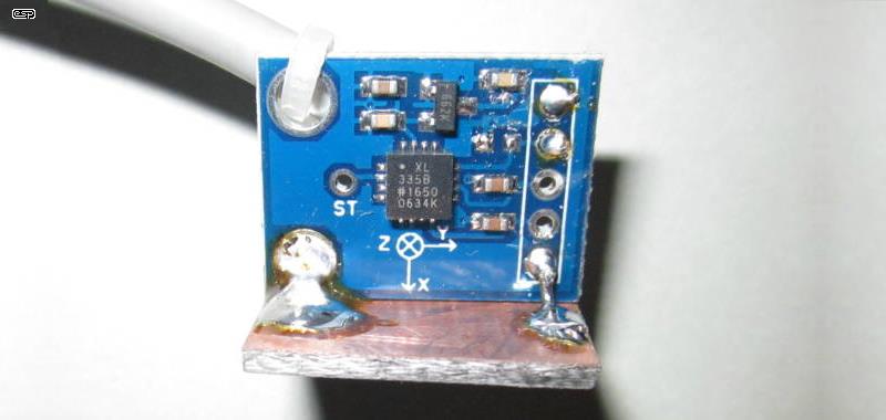
Figure 2 - Accelerometer Adapter Board
The PCB is available from a number of suppliers (including eBay), but be aware that you must get the ADXL335 or XL335) version. There are several others that look similar, but they use a digital IC that requires a microcontroller and a DAC (digital to analogue converter) to get an audio output. This is more than merely 'inconvenient', as it makes a simple project far more complex and it may not even be able to provide a useful audio output.
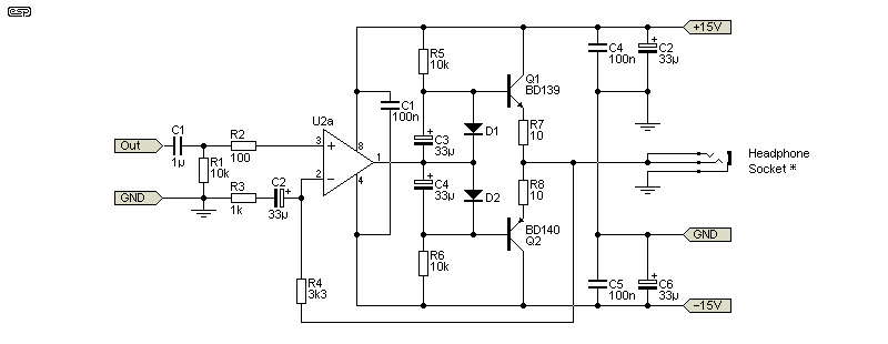
The headphone amp is based on P113, and you can use a P113 board (either fully populated or just one channel). You can build it on Veroboard quite easily, and if you do that you can use a single opamp (even a μA741 is perfectly acceptable in this role). Note that the pin numbers shown are for a dual opamp! The headphone socket can be either 3.5mm or 6.25mm, depending on your preference.
There are no parts of the circuit that are critical, with the exception of the bypass caps (Cb1-Cb3). Cb3 will ideally be a multilayer ceramic cap (MLCC) if the opamp is even reasonably fast. It can be omitted if you use a μA741 if you wish, but I prefer to use it wired across the supply pins of any opamp, however pedestrian. If a shorted output is likely I'd use a 22Ω resistor in series with the output. The P113 circuit is passably 'safe' with a shorted output, but only if you don't set the volume to maximum trying to get a signal.
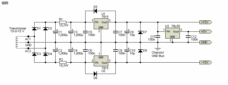
Figure 4 - Power Supply (Linear)
The power supply is conventional, and is based on the P05-Mini. A 78L05 is added to get the regulated supply for the ADXL335. It has an regulator on the PCB, but the quoted maximum supply voltage for most boards is 5V, so this needs to be provided. The 78L05 also requires bypass caps at the input and output to prevent oscillation, and these are shown as C11, C12. A reverse diode isn't needed for the 5V output because there is very little capacitance at the output.
Calibration is optional, but having a defined output of around 1V/g may be useful. The two test points are shorted for calibration, so both stages provide DC gain. I have to assume exactly 1.5V quiescent output from the ADXL335 with zero g, and the output of the filter should be 5.2V DC. Place the accelerometer base on a level (±1°) surface, and the output should fall to 4.2V (±10mV for 1% accuracy). Move the accelerometer base to the underside of the same level surface, and the output should rise to 6.2V.
If you get something different, VR1 needs to be adjusted to increase or decrease the gain of U1a as needed. This is an iterative process, because the wanted signal is not independent of the quiescent voltage because both are amplified by the same opamp. If the gain is changed, the quiescent voltage and the measured output will both change. I won't try to provide examples, but if the above process is followed you should be able to get a fairly accurate setting with about 2-3 adjustment/ measurement iterations.
As noted earlier, calibration is optional, and if you don't want to mess around you can replace R2 and VR1 with a 1.8k resistor, which sets the gain of U1a to 1.55. This will probably be more than accurate enough unless you have a critical application. Should that be the case, you won't be trying to build a precision accelerometer with a Chinese/ Taiwanese clone of the ADXL335 anyway. 
This project can be considered a 'super stethoscope', as it provides much the same functionality, but with more flexibility than a microphone-based stethoscope. It's not something that will be used every day unless part of your job is identifying problems with machines. Noise and vibration are easily detected, and it's ideal for listening to bearings and detecting faulty ones. For speaker-builders, there's nothing that comes close for listening to (or viewing on a scope) panel resonances and other anomalies.
The original Project 181 unit I built many years ago was used for just that, and the page for it shows screen captures of various speaker box panel resonances, along with other tests I performed. While this version uses a more complex power supply (±15V vs. +12V), the extra functionality (i.e. the headphone amp) is well worth it. The overall cost difference is not great, and this new version has the advantage of a defined output of 1V/g if you choose to calibrate it, so you can measure the actual g-forces experienced.
The ADXL335 (and the clone versions) have a typical maximum (peak) range of ±3.6g (the minimum is quoted to be ±3g), which will accommodate all but the most extreme vibrations. Any equipment subjected to this level of vibration continuously will almost certainly fail, so there's (usually) no need to be able to measure more than this. If you measure an output of ±3V peak at the output, that's close to the limit of the range, and any more will cause the ADXL335 to clip. The IC itself is claimed to be able to survive 10,000g - that's pretty extreme, so even if it falls on a hard surface it should be unaffected.
 Main Index
Projects Index Main Index
Projects Index
|