
|
| Elliott Sound Products | Project 148 |
 Main Index Main Index
 Projects Index Projects Index
|
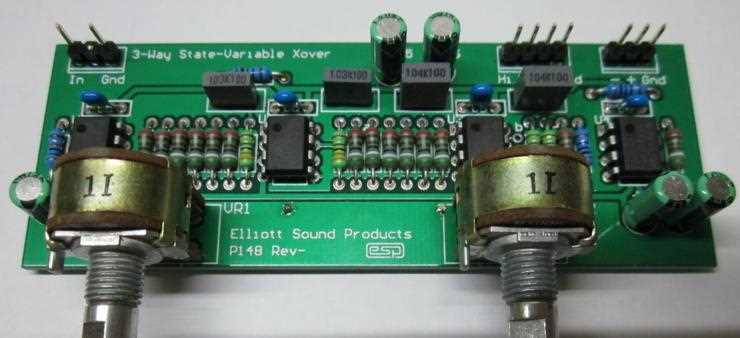
 PCBs are available for this project. Click on the PCB image for details.
"Not another crossover!" - I can almost hear the cries of anguish  . This one is different though, because it's continuously variable over a wide range, and maintains perfect level balance as the tuning pot is changed. It uses a readily available dual-gang pot, and needs no fancy parts that may be hard to get. Although it is perfectly suitable for use in a hi-fi system, I expect that the most popular usage will be for testing, allowing you to adjust the crossover frequencies for the best match for the drivers being used.
As a test system, I used an almost identical arrangement for many years, and it served me well for aligning everything from large, fully horn-loaded PA systems (intended for music reinforcement) down to small 2-way speakers as might be used for budget hi-fi systems or near-field monitoring in studios. The initial alignment of my main speakers in my hi-fi system was done using my trusty variable crossover.
The 'prototype' for this design is now over 40 years old and it has never missed a beat ... it's still being used. A modified form was also used in my hi-fi system for many years, until I built the current system using a 3-way Project 09 24dB/octave crossover (Linkwitz-Riley alignment).
With the design shown here, you can adjust the frequency and also the Q if desired. This lets you compare a 'traditional' Butterworth alignment to Bessel or Linkwitz-Riley. The rolloff is 12dB/octave, and this is for two reasons. Firstly, steeper slopes require a far more complex circuit and since state-variable filters are fairly complex to start with, you end up with something that is very difficult to build without a PCB. Secondly, multi-gang pots are needed, and they need fairly good tracking across the gangs. As most electronics enthusiasts have found, multi-gang pots are almost impossible to obtain.

I can say with complete certainty that assembling a state-variable crossover on Veroboard is a pain. However, I can say with equal certainty that the end result is exactly as expected, and it works perfectly as described. I made my test version using a 100k pot which gives a huge tuning range, and it's almost scary that you can move the pot while listening to the summed output and hear ... nothing. Despite the phase shifts as the pot is rotated, the sound doesn't change, and the summed response is flat to within better than 0.5dB from DC to 100kHz (using NE5532 opamps). I couldn't measure the distortion as it's below my measurement threshold, and it sat resolutely at 0.02% (the residual from my oscillator) at all pot settings and any sensible frequency and output level.
I recently changed the resistor values from 10k down to 5.6k to minimise thermal noise. In reality it probably makes little difference, so you can use 10k (or any other sensible value) resistors if you prefer. NE5532 opamps can drive low impedances easily with no increase in distortion, but very low values may cause premature overload. High values cause increased noise, and anything above 10k isn't recommended.
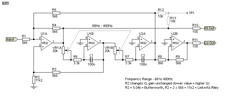
The state-variable filter is one of the most flexible topologies available, but it is comparatively complex, with several separate feedback paths that can make it somewhat confusing to analyse. Fortunately, there are relatively few different component values needed, with only a few deviations that are used to determine the frequency. In case you were wondering, U2B is an inverter, and that's needed because like all 12dB/octave crossovers, one output is 180° out-of-phase with the other. The inverter is used so the two outputs are in phase.
The state-variable filter itself uses U1A, U1B and U2A. It consists of a summing amplifier (U1A) followed by two integrators (U1B and U2A). The summing amp receives the input signal, and has three feedback paths. The first is local, and is negative feedback via R4. The second feedback loop is from the first integrator, and the third loop is from the final integrator. The complex mix of feedback voltage and phase produces a high-pass output at the output of U1A, a bandpass response from the output of U1B, and a low-pass output from the output of U2A.
High and low pass outputs are phase-coherent (although one output must be inverted), and in the circuit shown the output at any frequency is in phase from the two outputs. The output from U1B (bandpass) is not used and is not actually useful. It has a 90° phase shift, and although it can be used if you really want to, its bandwidth is too narrow to be useful, and the rolloff is only 6dB/octave. Bandwidth is also fixed by the filter Q, and the bandpass output is unsuitable for use with a midrange driver.

In the arrangement shown in Figure 1, it is assumed that the input will be from a low impedance source, such as a buffer opamp or a low impedance preamp output. If a non-zero source impedance is added to R1, this changes the gain and the Q of the circuit. Perversely, reducing the value of R1 will increase gain but reduce the Q, and vice versa. The Q can be changed without affecting gain by adjusting the value of R2. As shown, Q is 0.5, so the filter has a sub-Bessel (Linkwitz-Riley) response, with the two outputs 6dB down at the crossover frequency.
With a dual 20k pot and other values as shown, the frequency can be set anywhere between 68Hz and 480Hz. The range can be extended by reducing the value of R6 and R7 (3.3k), but making the value too small is not recommended. If reduced to 2.2k, the frequency range is from 72Hz up to 723Hz. TP1 is shown so you can get an instant and very accurate check of the crossover frequency - the signal will all but disappear at the frequency to which the filter is tuned. By adjusting your audio oscillator until the signal at TP1 falls to (close to) zero, you can then measure the exact frequency. If this isn't needed, then omit R12 and R13 (these test points are not present on the PCB).
Although it's far better if the two gangs of the pot track perfectly, a small error won't generally cause a problem. In most cases, the tracking should be good enough to ensure that the summed output response is flat to within 0.5dB (assuming Linkwitz-Riley alignment).
The ability to adjust the Q is probably only slightly useful, and with R2 at 11.2k (typically 2 x 5.6k resistors in series) the Q is 0.5 - Linkwitz-Riley. Intermediate values of Q are of no benefit, but provision for a Butterworth filter may be of value. A Butterworth filter has a Q of 0.707, and that requires that R2 be 5.04k. This means that the summed outputs will show a 3dB rise at the crossover frequency which is not generally considered useful these days. R2 can also be 11k or 12k, and passband ripple is below 0.2dB - much less than the variations of even the best loudspeaker drivers.
If C1 and C2 are reduced, the crossover frequency is increased. For example, using 10nF will give you a frequency range from 680Hz to 4.8kHz. This is more than enough range for crossing over a tweeter, so great care will be needed to ensure that your test tweeter isn't operated below its rated minimum frequency. You can change the values if you like, by reducing C1 and C2 further and changing R6 and R7 to limit the range. You might want to change the caps to 4.7nF, which will give a range from 1.45kHz to 10kHz.
The crossover frequency is determined by the value of the capacitor and series connection of the pot and R6/ R7. Calculating the frequency uses the traditional formula for a resistance/ capacitance filter, so with the values shown and the pot at maximum resistance (20k + 3.3k), the frequency is ...
f = 1 / ( 2π × R × C )
f = 1 / ( 2π × 23.3k × 100n ) = 68.3 Hz
With the pot at minimum resistance, the frequency is ...
f = 1 / ( 2π × R × C )
f = 1 / ( 2π × 3.3k × 100n ) = 482.3 Hz
It should come as no surprise that the calculated and simulated frequencies are the same (I ignored the fractional part of the frequency in the description above). You can change the frequency range by changing R6 and R7, and/ or C1 and C2. Both resistors must be the same value, and likewise for the capacitors. Use the above formula to calculate the frequency for any R/C combinations at various pot settings.
The basic 2-way arrangement shown in Figure 1 is also ideal for a variable sub-woofer crossover, however you would need a 4-gang pot to build a stereo version with a single control. In that case, the bass (low pass) outputs would simply be summed with a pair of 2.2k resistors.
For experimental work, in most cases a 3-way crossover is the most practical. It's easy enough to scale the circuit shown below to have as many frequency bands as you like, but the complexity will increase and there is unlikely to be much point. It's very rare that you would ever need more than 4 frequency bands, and even that won't be needed in 99% of cases.
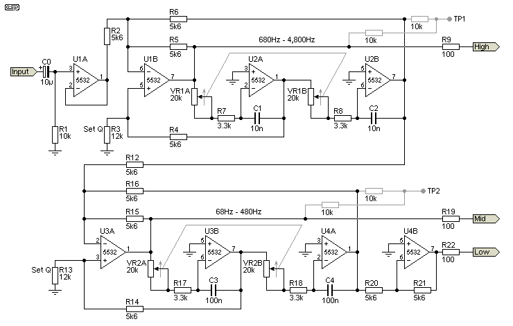
The circuit for a full 3-way variable crossover network is shown below. It's mono, so you'd need to build two to get stereo. Unfortunately, each channel's crossover frequencies must be set independently - again because 4-gang pots are very hard to get. If being set up for a permanent installation it's simply a matter of using fixed resistors instead of pots. The last thing you need is for someone (child or adult) to start playing with the pots, then asking "What do these do?".

It looks far more complex than P09 for example, and that's certainly true. The advantage is that you can change the crossover frequencies with the turn of a pot, something that isn't possible with the Sallen-Key filters used in P09. It might seem odd that the inverter stage is used on the bass (low pass) output. You would normally expect that it would be used on the midrange output, but that neglects the fact that the input opamp of the second filter (U3A) is inverting.
If you wish to change the filter Q, change the values of R3 and R13. As with the previous example, 5.04k gives a Butterworth response which will give a 3dB peak in the summed outputs. The ideal value for R3 and R13 is 11k2, but if you don't care about a very small ripple in the summed response (less than 0.2dB), R3 and R13 can be 12k as shown (or you can use 11k, which is a little better). The ripple created will be significantly less than that from even the very best loudspeakers in perfect enclosures.
The state variable filter is not easy to analyse, and in general the easiest way to test ideas or changes is to either build one on a prototyping board or simulate the response. While the latter approach is fast and gives very good results, it's never as satisfying as seeing (and hearing) the filter working in 'real time'.
Note that the test points shown are not included on the PCB.
 | The pinouts for a typical dual opamp is shown for reference. This is pretty much an industry standard, and nearly all dual opamps use this pin configuration. As always, I suggest that you download the data sheet for the devices you intend to use to double check. Power to pins 4 (-VE) and 8 (+VE) must be bypassed with 100nF ceramic caps between each supply and earth/ ground. Supply connections are not shown in the above drawings. |
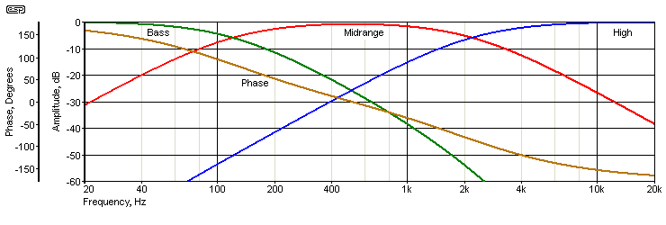
The amplitude response with the three outputs summed is flat, and the response from each output is shown, along with overall phase shift. The crossover frequencies are 120Hz and 2.18kHz for this example. The phase response will change when the xover frequencies are changed, as you'd expect.

The overall phase response shows a change from (nominally) +180° at 20Hz, changing to -180° at 20kHz. That's a total phase shift of 360° over the full audible range. While this may look 'bad', it's perfectly normal, and will be the same for any 3-way, 12dB/ octave filter with Linkwitz Riley alignment. This is completely inaudible as a static phase shift, and claims that phase is audible can be ignored. It's only audible if it changes (usually cyclically) and while it's changing a small pitch shift may be heard if it changes quickly enough.
All IIR (infinite impulse response) active filters do the same thing, and it doesn't matter whether the filter is active (including digital) or passive. Digital FIR (finite impulse response) filters can be designed to have no phase shift (otherwise known as constant group delay), but they include a time delay. This may be audible if the filtered and unfiltered signals are presented to the ear simultaneously, leading to deep nulls in the response.
Despite being "yet another crossover", this is a fairly unusual design but one that is a good fit with others in the ESP projects list. Fully variable (in 'real time') crossovers are not common in the DIY area, primarily because they require multi-gang pots that are hard to get. This project doesn't solve that problem, but you can use separate crossover tuning pots for left and right channels.
It is possible to use CMOS analogue switches in place of the pots, used as PWM controlled variable resistors. While this approach certainly works, I suspect that most people who are into DIY hi-fi will be somewhat wary of introducing high-frequency switching into the audio path. The advantage is that multiple channels can be controlled simultaneously, but the disadvantage is that there will always be a small residual of the switching frequency on the outputs. Switching needs to be at the highest practical frequency, and based on simulations it needs to be no less than ~500kHz but preferably higher. The main distortion contribution is due to aliasing, although CMOS analogue switches are not benign. Because the system uses switching, it's sampling in the analogue domain - rather than converting to digital. I do not plan to introduce a project using this technique.
At most settings that will be used and with typical input and output voltages, distortion can be expected to be well below 0.01%, and it only becomes worse with high signal levels (greater than 3.5V RMS which may create opamp clipping). As noted earlier, it's a circuit that is presented primarily as a tool for experimentation - there are several likely uses for it that I can think of, and I hope that readers find it as useful and interesting as I did when I first experimented with it way back in the late 1970s.
As noted in the introduction, I've been using an older version of the 3-way circuit for close to 40 years. It's still fully functional and is part of my workshop equipment. It's not in daily use, but is far easier to set up and use than the digital crossover that I sometimes use for determining the ideal crossover frequencies for loudspeaker drivers. For a speaker builder it's invaluable - even if the final crossover network will be passive (not that I recommend this approach of course). 
 Main Index Main Index
 Projects Index Projects Index
|