

|
| Elliott Sound Products | Loudspeaker Cable Characteristic Impedance |
 Main Index
 Articles Index
What is the effect of the characteristic impedance of a loudspeaker cable? Is it important to match the cable to the speaker load impedance, or is this simply a marketing ploy?
Much has been said by many cable vendors about loudspeaker cables characteristic impedance, with claims that it should match the speaker impedance for 'optimum results'. Likewise, there is also a great deal that we are not told, and this is of much greater concern.
One thing the cable vendors have completely neglected to point out, is that the characteristic impedance is only important (and relevant) when the source impedance, cable impedance and load impedance are all matched. Having an extremely low impedance at one end (the amplifier) and a variable impedance at the other (the majority of all loudspeakers) makes true matching impossible.
Having said that, even with a very low impedance at one end of the cable, most cables can be made to have a passable match at low to mid radio frequencies (RF) by terminating at the far end only. (Note that at the frequencies we are looking at they are not really transmission lines, although I may use the two terms interchangeably.) Some degree of 'matching' may be (to a degree) because the amplifier's output impedance rises as the frequency increases, but all amplifiers will be different in this respect.
To improve the impedance match and reduce the reflections that are caused by an unterminated transmission line, some (but all too few) vendors recommend a Zobel network - a resistor and capacitor in series, typically 10Ω and 100nF. This, they tell you, should be installed at the speaker end of the cable. The usefulness of this is not always optimal as will be shown later in this article, but in most sensible cable constructions, it will do no harm. For some of the more exotic constructions, a far-end Zobel is essential, however some may be poorly designed.
Another 'minor' detail that the cable vendors fail to mention is that the characteristic impedance of a cable varies with frequency. At DC, the characteristic impedance of all cables is infinite (for all intents and purposes), and the rated impedance is usually not reached until the signal frequency is well above the audio band - typically around 100kHz or more, depending on the cable's construction and length. Any cable consisting of parallel or concentric conductors (including flat conductors, multi-wire ribbon cables and Litz cables) acts as a transmission line at high frequencies, or (at least to a degree) if the line is extremely long (usually several to many kilometres). All transmission lines have a characteristic impedance, and this is a basic principle of physics - at issue is the flippant way many vendors handle the truth.
But wait! What is characteristic impedance anyway? The characteristic impedance of a cable (Zo) is a complex function of the diameter (or dimensions if other than round) of the conductors, their relative spacing, and the insulation material. Simplified, it is determined (for high frequencies) as Zo = √L/C, where Zo is characteristic impedance, L is inductance and C is capacitance.
Note that Zo is a constant, and is independent of the length of the cable. An ideal cable (for a high powered audio system) will have low inductance, low capacitance and low DC resistance (DCR), but it is important to understand that the Zo of the cable is usually completely unimportant at audio frequencies. It's also important to understand that any cable can be driven by zero ohms (or close to it), and there will be no reflections provided the terminating impedance is close to the cable's characteristic impedance. This is seen clearly in many of the graphs below where a 'termination' Zobel network has been connected.
In order to obtain a low characteristic impedance, it is necessary to have very low inductance and relatively high capacitance, and the high capacitance may impose serious constraints on the amplifier. Indeed, many amplifiers will become unstable if there is sufficient capacitance connected directly to the output, causing oscillation which may damage the amplifier. As described above, regardless of anything else, the cable does not act as a true transmission line at audio frequencies, and claims to the contrary are fallacious.
For these esoteric cables, their high capacitance dictates that there will be the opportunity for the insulating material to contribute its 'sound' to the overall signal fed to the loudspeakers. It must be pointed out that this is hotly disputed by many engineers, and there is no conclusive evidence that any one dielectric material is 'sonically superior' to any other. I know of no properly conducted Double-Blind Test (DBT) where the listening panel was able to pick the difference with greater than 50% accuracy - i.e. pure chance. However, the possibility cannot be discounted, so it is worth mentioning.
For RF applications, or for extremely long signal runs, such as telephone circuits, impedance matching is essential. Matched impedances mean that the source, cable and load impedances are all the same. For video, the standard impedance is 75Ω, so the output impedance of a video line driver will be 75 ohms, 75Ω coaxial cable is used for connections, and the receiving end is also 75Ω. There are nearly always mismatches because of the use of RCA connectors (typically about 40Ω impedance), but in a domestic installation this usually does not cause a problem, since the cable runs are relatively short. It is generally accepted that if the transmission line length is less than around 1/10th of the shortest wavelength, then impedance matching is not overly important - again, we will see that this is not necessarily the case, since an audio amplifier's bandwidth can easily exceed the audio bandwidth by a factor of 10 or more - the effects may not be directly audible, but amplifier oscillation is to be avoided under any circumstances.
Matched impedances ensure maximum power transfer from source to load, and this is obviously very important for RF transmitters and telephony applications. It is completely irrelevant for a solid state audio power amplifier however, since the drive principle (known as voltage drive, or constant voltage) does not rely on maximum power transfer, but relies instead on the amplifier maintaining a low output impedance with respect to the load.
The ratio of amplifier output impedance to load impedance is called 'damping factor', and with modern amplifiers it can easily exceed all normal (real life) requirements. Power amplifiers usually have an output impedance of between 10 and 100 milliohms, giving damping factors of between 800 and 80 (respectively). Valve amplifiers may have a damping factor as low as unity (i.e. the amplifier's output impedance is equal to the load impedance). No amplifier manufacturer quotes damping factor with cables attached, and in reality it is always less than claimed.
The damping factor (DF) figures are theoretical, and are rarely (if ever) achieved in practice. For the remainder of this article, I will use the output impedance of my simulated amplifier for reference (about 24mΩ - milliohms). This figure is passably realistic in a real world amplifier, but the internal wiring will increase it somewhat.
Even though most power amplifiers are limited to at most a few hundred kHz or so, there can still be some energy at higher frequencies - typically noise. What often happens is that an amp can be quite stable with a capacitive load and no signal, but as soon as it is driven it 'excites' the whole system, and it then bursts into sustained oscillation.
It is almost impossible for any amp to reproduce high levels at extremely high frequencies, and they are not present in the source material. This has never stopped an amp from oscillating though, usually at a frequency high enough to cause simultaneous conduction of the power transistors, since they cannot switch off quickly enough, and both will be turned on at the same time.
This simultaneous conduction is what causes damage, since the output devices heat up very quickly and may go into second breakdown - if that happens, then it's all over - the amplifier will fail with blown output devices. Anyone who has had an amplifier on a test bench and supplied it with an input signal at 100kHz or more will have seen this - even with no load, the amp will draw a lot of current even at low output levels. If maintained for any period of time, the amp will fail.
The details of any test or simulated test are imperative for a full understanding. With this in mind, the following section describes the simulated amplifier that was used, the unloaded frequency and phase response, and the simulated cable and loudspeaker details.
The simulated amplifier schematic is shown in Figure 1. The phase angle at unity gain - at round 10MHz - is 150° (or a phase margin of 30° - i.e. a very stable amplifier). Phase is relatively unaffected by load resistance, or the presence of the amplifier's internal Zobel network. The latter is to ensure stability with an inductive load, but is ineffectual against capacitive loading.
To verify that the simulation represents reality to an acceptable degree, a 100nF capacitor placed across the output will cause instability, and this is substantially in agreement with empirical data on real amplifiers. It is worth noting that the simulated transistors have a much wider bandwidth than the majority of real life transistors, and this shifts the results up in frequency. Most of the amplifier effects seen at 10MHz will actually occur at perhaps 1MHz. All transmission line effects (in particular the peaks caused by impedance mismatches are exactly as shown - these are determined by the cable and its length, and are independent of the amplifier. Also note that many amplifiers will oscillate with a great deal less capacitance than the simulated version.
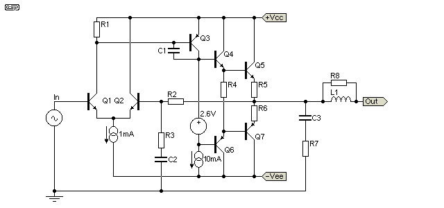
Figure 1 - Simulated amplifier
The amplifier used for these simulations was as shown in Figure 1 and it is a completely conventional (if somewhat simplified) circuit, typical of those used for hi-fi applications (in fact, fairly typical of the majority of amplifiers for any purpose). The closed loop frequency and phase response are shown in Figure 2. The phase margin (the number of degrees of phase shift between the actual unity gain frequency (Ft, or transition frequency) and 180 degrees. At 180 degrees phase shift, an amplifier's negative feedback is reversed in phase, so becomes positive feedback. If the amplifier has gain greater than unity at that frequency, it will oscillate.
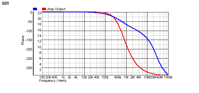
Figure 2 - Frequency and Phase Response
Neither frequency response nor phase response are affected by a resistive load. Inductive loads (of less than a few hundred µH - micro Henrys) are compensated by the Zobel network C3 and R7, with typical values being 100nF and 10Ω, although this varies to some degree with the particular design. For reference, the simulated amp's output impedance at selected frequencies is shown below.
| Frequency | 1 kHz | 20 kHz | 100 kHz | 1 MHz | 2 MHz |
| Impedance | 24 mΩ | 25 mΩ | 45 mΩ | 444 mΩ | 515 mΩ |
In many amplifier designs, the speaker line capacitance is 'decoupled' from the amplifier by the combination of L1 and R8. Again, fairly typical values are 800nH in parallel with 10Ω, but as always, this can vary. Inductance above 1 or 2µH is rare, as it will have an audible effect on the overall frequency response, especially with low impedance speakers (for example, a 10µH inductance causes a 0.4dB loss at 20kHz and a 4Ω load, and that's with no cable at all). The resistor damps the Q of the inductor to prevent (or at least minimise) the possibility of the inductor and cable forming a resonant circuit. This network can be replaced with an 0.1Ω resistor, but that approach is rare. Simulations were performed without the series inductor, since its presence swamps the very effects we are looking for so that amplifier instability can occur. The amplifier's RC Zobel network was retained for all simulations - very few amplifiers will be stable with any normal speaker and load without this network.
Note that in some of the simulations that follow, the phase margin may appear adequate to maintain a stable system. This is a direct result of simulations and real life failing to coincide, and it is imperative that you understand that the results shown may appear to 'trivialise' the effects. Cables such as Sample #3 will cause most amplifiers to become unstable - the phase results shown also appear to be static, but in fact they change with amplitude, and anything that creates a radical phase shift at the amp's output will almost certainly cause oscillation in real life.
Continuous oscillation will often lead to an amplifier running much hotter than normal. The effects are not always audible, but in the majority of cases you will hear that the amp just doesn't sound 'right'. Any amp that is oscillating is at serious risk of spontaneous self-destruction, and it's a condition that must never be allowed to continue.
 | Predictably, the above usually doesn't apply to Class-D amps, because they rely on oscillation for their operation. Class-D amps are not usually affected by cable capacitance, but it may be high enough to detune the output filter and create subdued or accentuated high frequency response. |
Oscillation may not be 'steady state', and may appear at certain points of the output waveform. Oscillation of this nature is referred to as 'parasitic oscillation'. This can be worse than an amp that oscillates continuously, because it may only show up with a specific set of load conditions. It usually sounds horrible, but in some cases it can go (almost) un-noticed because it may only occur during certain passages in music, or at a particular level where the effects become audible. While I don't know of any amp that's died as a result of parasitic oscillation, it is highly undesirable and any amp that suffers from it should be repaired.
Figure 3 shows the schematic of the simulated cable, and the 'far-end' Zobel network. Also shown is a 'near-end' (i.e. at the amplifier) Zobel, but this is not needed for the most part. It is recommended if you use a series inductor at the amplifier output (or if you know that one has been included by the manufacturer). Leaving it out of circuit will normally have little or no effect on amplifier stability, and only serves to terminate the cable properly at very high frequencies.

Figure 3 - Simulated Cable & Termination
Although most people (myself included) may not like the idea of a ceramic capacitor in the audio path (for the 'C' element of the Zobel networks), ceramic is actually the best choice for this application. It is important that the inductance of the capacitor (primarily lead and capacitor body length) is as low as possible, or response will be limited at exactly the frequencies where it becomes important. Even if the capacitor is non-linear (which is a characteristic of ceramics), it is in parallel with the load and amplifier output, and will have no effect on the audible part of the signal. Remember that we are dealing with a small capacitance (100nF is typical), and its reactance (or impedance) is 100Ω at about 16kHz (80Ω at 20kHz). Even a non-linear device with that much impedance will not affect any known amplifier, and the cap is also in series with a resistor, further reducing its already negligible contribution.
The use of 'audiophile grade' polypropylene or other film caps is discouraged, since their performance at several MHz is degraded by internal inductance (which determines the 'self resonant' frequency of the cap). The capacitor(s) should be rated at a minimum of 50V AC (or 100V DC), although the voltages actually developed across the caps should be much lower than this at any frequency.
The resistor should be a carbon or metal film type, and a rating of 0.5 - 1W is normally quite sufficient. The power developed with normal signal will be a lot less than 0.5W, even with powerful amplifiers. If you feel that you must use a wirewound resistor, then it must be a non-inductive type.
The important part of this exercise is to show that if a Zobel (matched to the cable's impedance) is used at the 'far end' (i.e. at the loudspeaker terminals), then there is no requirement for an inductor at the output of the amplifier. It's usually included to ensure that amplifiers don't misbehave with high capacitance cables, but if the cable is terminated properly, the inductor is no longer necessary.
The loudspeaker is a two-way, fully impedance compensated design. It uses a Zobel network to null the woofer's rising impedance caused by voicecoil inductance, and a tweeter resonance compensation circuit. This is based on a simulated loudspeaker system used by Jon Risch (the designer of Cable Sample #2) for some of his measurements and simulations, and is a reasonable approximation of a real speaker system. A resistance (or a much simpler simulated loudspeaker) could have been used, but this would not provide a 'real life' experience for the simulations.
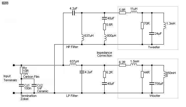
Figure 4 - Simulated Loudspeaker System
The 'woofer' is in a sealed box, so has only one low-frequency impedance peak. It's a relatively benign speaker, having a low frequency resonance of 27Hz, and a minimum impedance of 3.9Ω at 430Hz. The impedance is over 6Ω for most of the audio band. At very high frequencies it behaves like most speakers, having an impedance of over 65Ω at 1MHz, with the impedance rising further as frequency is increased. By 1.5MHz impedance is 100Ω, rising at 6dB/ octave (impedance roughly doubles with each doubling of frequency). In short, this is a well behaved loudspeaker which behaves exactly as one might expect.
The speaker is shown with a 'generic' Zobel termination, consisting of Rz, Cz1 and Cz2. The capacitors should have very good characteristics up to several MHz, and this is one area where there is a benefit if a second (smaller) ceramic capacitor is connected in parallel with Cz1. The two capacitors must be rated to handle the full amplifier output voltage, and ideally with something to spare. Caps rated for 630V DC will be fine for most amplifiers, and the resistor should be carbon film. Wirewound types aren't needed, and their inductance will cause a mismatch. The leads should be as short as possible, and all parts should be wired directly to the speaker input terminals.
The simulations are all based on the majority of speaker systems, where this termination network is not included. Various terminating impedances are shown, and it turns out that the Zobel shown above will work with almost any cable, regardless of its actual characteristic impedance.
Three different cables were used in the simulations that follow. It is important to note that these are simply used as representative, and no conclusions should be formed when comparing to manufacturer's stated (or claimed) data. No endorsement is implied for any configuration, manufacturer or anything else, other than a final recommendation below.
| Sample | Resistance | Inductance | Capacitance | Impedance | Reference |
| 1 | 11.15 mΩ | 626.64 nH | 68.90 pF | 95.37 Ω | 12# Zip |
| 2 | 14.57 mΩ | 219.82 nH | 114.83 pF | 43.75 Ω | Jon Risch |
| 3 | 14.44 mΩ | 32.81 nH | 1640.42 pF | 4.47 Ω | Goertz MI 1 |
| 4 * | 37.50 mΩ | 975.00 nH | 54.25 pF | 134 Ω | Oz 'Fig. 8' |
* #4 was something of an afterthought, and is described further down this page.
All values are per metre of cable length, and the simulations were performed using a 4 metre length (a little over 13 feet), as this is fairly typical of most domestic installations. As cables are made longer, the effects described occur at lower frequencies. With most cables, the velocity factor is between 0.6 and 0.8 (meaning that the signal travels slower than it will in a vacuum). Velocity factor is always quoted for RF cables, but I've never seen it mentioned for speaker cables. While it may seem unlikely, it's a very real phenomenon, and for the cables simulated here I've assumed a VF of 0.8, meaning that the cable will delay the signal by about 17ns (however, this varies with different cable constructions).
In the following sections, a great many possibilities are looked at, and graphs of the response are provided. By necessity, these are smaller than optimum, otherwise the page would take 3 weeks to load. The effects of different combinations are very clear, and additional descriptions point out the areas of interest.
The first graph shows Cable 3. I selected this for the first simulation, as it is the most likely to cause amplifier instability with no termination Zobel. Although the radical changes in phase are quite visible, it is a little difficult to see the effect on the amplifier. It transpires that this cable produces an output phase on the amplifier of that is well outside its phase margin, at around 192°. That means that it will almost certainly cause the amplifier to oscillate, either continuously or at particular voltages and currents that cannot be predicted with any reliability. Such spurious oscillations generally cause an amplifier to sound distorted as they start and stop. Sustained oscillation often leads to amplifier output stage failure.
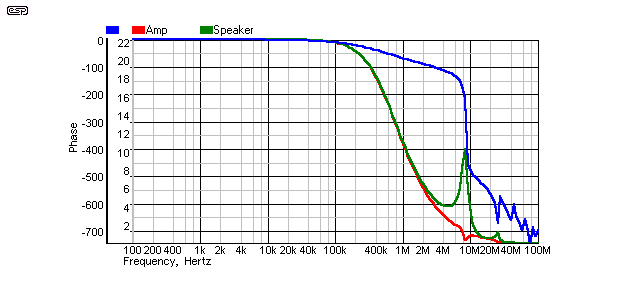
Figure 5 - Cable 3, No Far End Termination
As you can see, the cable has a large peak in the response at a little under 10MHz, and the phase response is savage. Each kink or discontinuity in the plot indicates a reflection, and note the phase angle - it shows 700° of phase shift at 100MHz!
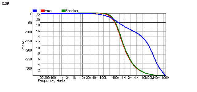
Figure 6 - Cable 3, Far End Terminated (4.7Ω)
After adding the far end Zobel network, as you can see here the cable's response decay is perfectly smooth with a 4.7Ω resistor. This is the optimum match, and is the value that should be used - not 10Ω as supplied (see below).
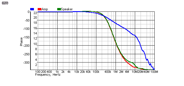
Figure 7 - Cable 3, Far End Terminated (10Ω)
Even 100nF in series with 10Ω restores the amplifier phase margin to normal (150°). As seen above, 4.7Ω is preferable, but the phase margin is barely affected.
The speaker end response has a small 'lump' with 10Ω, and phase goes 'wobbly' at above 20MHz. This is probably not a concern, and you will almost certainly get away with it. It is very evident that this particular cable should never be used without a Zobel at the speaker end, and it is equally obvious that the vendor does not really understand transmission line theory, since the Zobel networks supplied with the cable (and you have to ask!) are incorrect. This is not difficult to get right, and if they are off base with something a simple as a resistor value, I would be disinclined to believe their other material.
While the results aren't actually appalling, it is quite obvious that the performance is not as good as with the correct termination resistance. At this level (and since the impedance of the cable is quoted on the web site), I find it difficult to understand how they could have made such an error. Not that this manufacturer is alone by any means - 'experts' will emerge from the woodwork, suggesting a that 10Ω, 100nF Zobel is the panacea - it is, but only for 10Ω cables!
This seems to be the standard against which all other cables are judged, so it is next on the list. As you can see, there is a pronounced reflection at almost exactly the same frequency as before. This must be, since the cable (transmission line) is the same length, and the first reflection will occur at the same frequency. Small variations do occur, and are the result of differing velocity factors. Velocity factor refers to the speed at which an electrical signal passes through a cable. Typically, this is between 0.6 and 0.8 of the speed of light (3 × 10⁸ metres per second.)
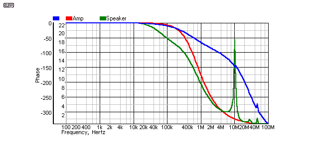
Figure 8 - Cable 1, No Termination
The response is relatively benign, despite the quite large peak at 10MHz. The reflection spike causes no change to the amplifier's phase response until it is above 40MHz and will have no effect. There is a very slight reduction of level at 100kHz (and down to 20kHz), but this is measured in fractions of a dB, so can safely be ignored. A greater disturbance to the in-room response will be experienced by moving the listening chair or a nearby coffee table.
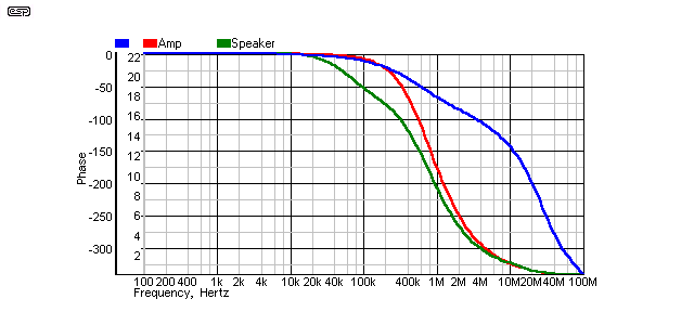
Figure 9 - Cable 1, Far End Terminated (100Ω)
This is a perfect result. There are no spikes, no response anomalies, and the amp's phase margin is unchanged. For the cost of a 100Ω resistor (close enough) and a 100nF ceramic capacitor, the cable is nicely terminated, and although virtually any amplifier will drive this cable with no ill effects even when unterminated, there is the potential to reduce RF pickup.
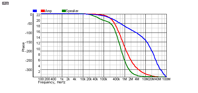
Figure 10 - Cable 1, Far End Terminated (10Ω)
It is apparent that a 10Ω termination impedance is 'sub-optimal'. In reality, it is not that bad, and the effects will almost certainly be inaudible. Something that is not obvious is a peak at around 10kHz - it is not large (about 0.1dB relative to 1kHz), and the top-end response is down by about 0.2dB at 23kHz (note that the effect will be a little worse with a 4Ω speaker). As a compromise, a 47Ω resistor will cause no major peaking, and presents a passable match to a wide range of 'zip' cables. Because these cables are already benign, they are much more tolerant of mismatch.
It was actually a reference to this particular cable on the Audioholics website that caused this investigation in the first place. Comments were posted and re-posted, as were claims and counter-claims. This design is also relatively benign, and I do not propose to cover all the issues raised previously - I am interested only in the cable's effect on the amplifier, and whether it is likely to cause instability.
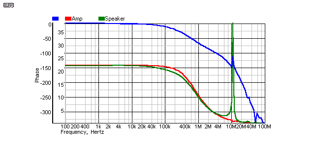
Figure 11 - Cable 2, Unterminated
As can be seen in Fig. 11, even when unterminated, the result looks pretty severe (note the height of the spike at 10MHz), but is not very much worse than cable #1. There is a phase anomaly at 10MHz, but the amplifier is well within its phase margin, and few (if any) amplifiers will be affected by this. Not as visible on the chart, but present nonetheless, is a slight broad peak in response centred on 5kHz. The amplitude is well under 0.1dB (0.04dB to be precise) and is insignificant. Amplifier phase margin is not affected, but cable response extends to over 100kHz - I can't hear that and nor can anyone else, but this also means that there is less rolloff with a lower impedance speaker.
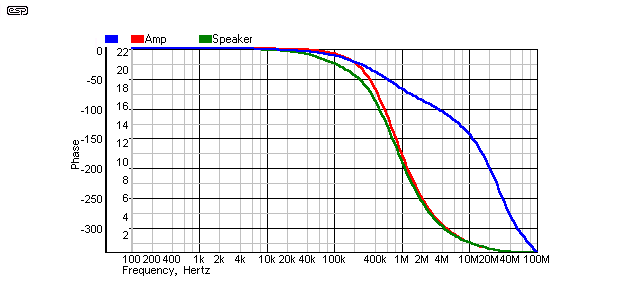
Figure 12 - Cable 2, Far End Terminated (39Ω)
Since this cable has a Zo of 37Ω, a 39Ω termination resistance is close to optimum. The response again is virtually flawless, and reflections are eliminated completely.

Figure 13 - Cable 2, Far End Terminated (10Ω)
Overall, this cannot be considered a bad result. In fact, the mismatch actually improves the response, although it is well outside the audio spectrum. That it is less than optimum is not at all obvious (although there are some tiny ripples on the phase response at above 20MHz), but amplifier stability is not compromised, and there is no peaking. Also obvious is the divergence of the amplifier and loudspeaker-end responses (also visible on the other graphs where impedances were mismatched), and this is a clear indicator of a mismatch - even if it is well outside the audio bandwidth.
My personal choice would be to use a 39Ω resistor, since that is a much closer match to the line impedance, but the resulting differences will certainly not be audible.
Using the decoupling RL network at the output of the amplifier will provide protection against all but the most radical of speaker cable designs, but it must be noted that it is a rather pointless exercise to spend a great deal of money to get cables with the lowest possible inductance, and then have to add an inductor to your amplifier so it doesn't oscillate.
The obvious (and recommended) cable constructions are samples 1 and 2, and both of these will give good performance for a very reasonable outlay. Cable sample #3 cannot be recommended, not only because of its high capacitance, but because it is much more expensive than the other two, and the actual benefits are somewhere between minimal and non-existent. If you can afford to purchase such cables, then that is up to you, but bear in mind that the manufacturer cannot even manage the correct value for the Zobel network that they supply. In my books, that does not qualify them for anything more than a shake of the head, a mild chuckle and "Not today, thanks".
Since I had the simulations all set up, I figured that a quick test of what is commonly known in Australia as 'Figure 8' cable (basically the same as zip cable) was in order. The standard 'hardware store' offering is not especially robust, being 22 strands of 0.022mm wire per conductor (0.75mm²). It is 240V insulated wire, commonly used for lamps and the like ('lamp cable'). I use this for basic test leads in my workshop, and the figures for a 4 metre length are ...
Resistance = 150 mΩ
Inductance = 3.9 µH
Capacitance = 217 pF
Impedance works out to about 134 Ω. This is a very benign cable, and I have never seen an amplifier oscillate because of it, so, what do the simulations say?
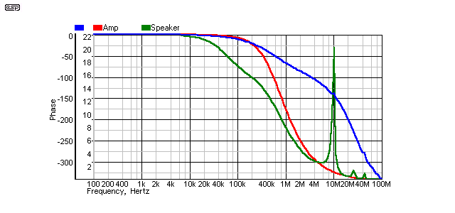
Figure 14 - 'Figure 8', No Termination
No surprises at all really. There is an obvious loss at 20kHz (still less than 0.5dB though), the spike that we now expect, and zero phase anomalies.
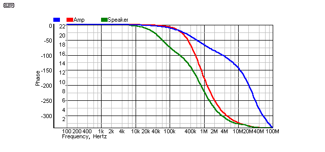
Figure 15 - 'Figure 8', 120Ω Termination
Again, this is to be expected. Response is -3dB at 67kHz at the speaker end, which actually will do me just fine, since I certainly can't hear the loss (less than 1dB at 20kHz). The termination again removes the spike in the response, and there are zero phase effects at the amplifier. It goes without saying (but I will anyway  ) that termination causes zero audible difference, however, in the presence of strong RF fields, a terminator should reduce or even eliminate RF interference. This is difficult to test because my workshop is nowhere near any RF sources powerful enough to cause problems.
It is worth noting that any of these cables will exhibit further anomalies and discontinuities if driven from an amplifier with infinite bandwidth. These have not been invented yet, so the amplifier-end mismatch is not a major problem, but if an inductance isolation network is used in an amplifier, then a second Zobel following the inductor is recommended. This ensures that the transmission line is terminated with the correct impedance at both ends for all frequencies above ~50kHz or so.
In addition, it was stated at the beginning of this article that characteristic impedance is irrelevant at audio frequencies. The frequency at which a pair of wires line starts to act like a transmission line is determined primarily by its length. Fortunately for the purposes of research, simulators can provide a signal source with zero impedance and infinite bandwidth, so the limitations of the physical world need not concern us. Using a 50Ω transmission line (purely for convenience), the following points are of interest ...
Now, let's look at each of these claims. If a cable acts like a transmission line, is properly matched at each end, and has essentially zero resistance, then 1V from the generator will result in 0.5V at the input of the cable, and 0.5V at the output, since the system behaves like a simple resistive voltage divider. The cable is irrelevant. I will spare you the tedium of looking at a graph with a straight line at exactly 0.5V from 1Hz to 100MHz, since it has zero interest value.
In order to highlight the resistive effects, I simulated a 100 metre cable, with 1Ω per metre DCR. This is obviously not a useful cable (at least not as a speaker cable), but it shows the effect very clearly. Figure 16 shows the test circuit, and current was monitored at the output of the AC generator.

Figure 16 - Transmission Line Test
In Fig. 17, you can see that the output current is clearly dominated by the resistance until the cable behaves like a transmission line. The current from the generator (AC) should be equal to V/R ... V is 1 Volt, and R (for the 100 metre line at 1Ω/ metre) is 200Ω (including the two external resistors). This works out to 5mA, and indeed, that's exactly what is measured - until the 'magic' frequency of 100kHz, where the current increases.
Above 1MHz, the current is 10mA (1V /100Ω), meaning that the cable resistance has disappeared! In the space of one decade in frequency, the cable has transformed itself into a true transmission line, where the signal is not conducted as such, but transferred by a waveguide (waveguides are usually just tubes for UHF signals [e.g. microwave], however a wired transmission line is also a waveguide). Naturally, the resistance never really disappears, but its influence is greatly reduced.
It is worth noting that a cable will never act as a true transmission line with a defined (and maintained) Zo unless its source and load impedances are equal to the line impedance. This means that no audio cable will ever be a transmission line, (almost) regardless of length, unless the amplifier output impedance, cable impedance and load impedance are all equal at all frequencies within the desired range. No known amplifier or loudspeaker system can meet these criteria. Alternatively, the cable may be infinitely long, however this is usually impractical in a domestic environment.
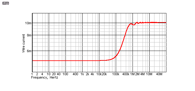
Figure 17 - Transmission Line Current Vs. Frequency
Obviously, the cable is just a pair of wires below the transition frequency, and your speaker cables (regardless of claims or cost) are exactly the same. In case you may want to simulate this effect yourself, I used DCR=1Ω, L=200nH and C=100pF per metre, and used a 100 metre line. A shorter line does exactly the same thing, but the frequency where it becomes a transmission line (rather than a couple of wires) increases as the line length is reduced. For a 10 metre cable, the frequency is 1Mhz, and for 3 metres this increases further to 3.3MHz. These effects were present in all the previous simulations, but were masked by the amplifier's rolloff.
To be fair, it is unreasonable to investigate these cables without looking at the frequency response, so the following tests were done. In each case, response at the far end (loudspeaker) was plotted in dB, with only the cables resistive component (red graph) and with inductance and capacitance included (green graph). Response plots were done from 10Hz to 100kHz, and it is obvious that there are some differences. The same simulated amplifier was used for all tests, so its influence on the response is included. Again, all cables were measured using a 4 metre length.
Even with the very worst cable (the Aussie 'Figure 8' lamp cable), response is dominated by resistance at low frequencies. The addition of inductance and capacitance actually improved matters for the 12 gauge zip cord and Figure-8, and the far-end Zobel makes no difference (it was included for all tests, and was 100nF in series with 100Ω).
For comparison purposes, I checked the 12 gauge zip cable with a 'perfect' zero ohm source. The maximum deviation was 0.106dB, and the predominant frequency was at 7.8kHz. This shows quite clearly that for most cable constructions, the amplifier's output impedance is a factor at low to medium frequencies. Cable inductance affects the signal at above 20kHz, while capacitance is not really an issue at all - other than its potential to make an amplifier oscillate if high enough.
The variation between a 'perfect' (or ideal) source having zero ohms impedance and response from DC to daylight, compared to an amplifier with 24mΩ output impedance is not great with any cable - the 12 gauge zip shows a variance of only 0.03dB (close enough) between the two sources, and this has the lowest DC resistance of the cables tested. Obviously, the lower the DCR of a cable, the more influence the amp's output impedance has on the overall result ... until inductance becomes the predominant factor.
Note that all response measurements were done using a nominal 8Ω load, and that inductance will have a greater effect if the load is 4Ω (or less). The following table shows the -1dB frequency for 8Ω and 4Ω loads, with a range of inductances from 1µH to 10µH.
| Inductance | 8Ω -1dB | 4Ω -1dB |
| 1 µH | 647 kHz | 325 kHz |
| 2 µH | 324 kHz | 162 kHz |
| 3 µH | 216 kHz | 109 kHz |
| 4 µH | 162 kHz | 82 kHz |
| 5 µH | 130 kHz | 65 kHz |
| 6 µH | 108 kHz | 54 kHz |
| 7 µH | 92 kHz | 46 kHz |
| 8 µH | 81 kHz | 41 kHz |
| 9 µH | 72 kHz | 36 kHz |
| 10 µH | 65 kHz | 32 kHz |
It is quite obvious that a total inductance of up to 10µH will be quite acceptable for the highest of fidelity with any loudspeaker that has a benign impedance at the high end of the audio spectrum, at either 4 or 8Ω. Most speaker systems are reasonably consistent at the high frequency end, but obviously there are exceptions, and these will cause audible differences.
These results are all simulated (rather than measured), since this is the fastest way to achieve the results, and the simulations will agree with reality very well. While there are other factors that are not taken into account (such as skin effect or insulation material 'soakage'), these are generally considered to be inaudible, and no proof has ever been offered that anyone can distinguish the difference in a DBT. That there are differences is undeniable, they can be measured quite easily with the right equipment, but any such effects are well below the noise floor and/or resolution of even the best amplifiers and speakers. Indeed, atmospheric changes will cause far greater variations in the signal you hear.
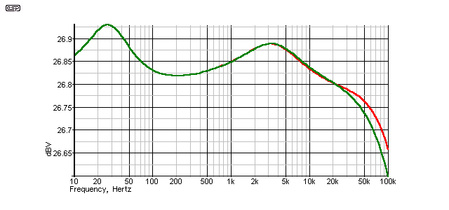
Figure 18 - Cable #3 Frequency Response
This looks terrible, until you notice the dB range. Total variation is from a low of 26.8dB at 20kHz to a peak of 26.93dB at about 27Hz (woofer resonance, and the highest impedance the loudspeaker presents). A total variation of 0.13dB. Midband level is 26.826dB at 200Hz.
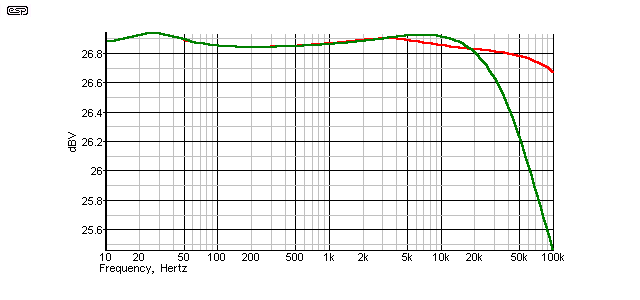
Figure 19 - Cable #1 Frequency Response
The zip cable looks better, and at a very small fraction of the cost. Minimum is 26.8dB at 20kHz and maximum is 26.93dB at woofer resonance - again, a total deviation of 0.13dB. The HF rolloff between 10kHz and 20kHz is 0.1dB (hardly woeful - find a tweeter that good!) Midband level is 28.84dB at 200Hz.
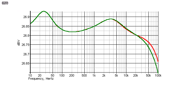
Figure 20 - Cable #2 Frequency Response
Cable #2 is again at 26.8dB at 20kHz, peaking at 26.93dB - a total variation of 0.13dB. Midband level is 26.82dB at 200Hz.
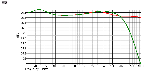
Figure 21 - 'Figure 8' Frequency Response
Last (in all respects) comes the Figure-8 cable, but at the equivalent of perhaps 14 gauge (US gauge numbering), one expects it to be less than impressive. Minimum level is 26.6dB at 20kHz, and maximum is around 26.91dB - a total deviation of 0.31dB. Midband level is about 26.68dB at 200Hz.
It is worth noting that none of these cables is 1dB down on midband level at any frequency up to 20kHz, and even the Figure-8 lead is only 1dB down at 50kHz - it is a rare tweeter indeed that will be anywhere near as good, regardless of price.
So, what do you get for your money with 'premium' speaker cables? Quite obviously, very little improvement is afforded by any of these cables over another - 12 gauge zip cable is cheap and easy to make into a speaker lead, Jon's cable is a little more expensive, and there is a fair amount of work involved, and the Goertz cable will set you back about US$200 a pair for 4 metre lengths (and maybe make your amplifier oscillate). Naturally, you can spend a great deal more (and still make the amp oscillate), but I don't see much point.
If it makes you feel better to have sexy looking cross-connected coax leads, then far be it for me to attempt to deny you that pleasure, besides, it might be fun to do (which is far more important). I still can't recommend the Goertz cable, as its capacitance is just too high. A Zobel tames that, but I would be reluctant to use it anyway, and I certainly wouldn't pay their prices for it!
In general, a 'bog standard' Zobel network consisting of a 10Ω resistor and 100nF capacitor in series should be standard, wired internally at the terminals of any loudspeaker. Most cables don't need it, but it does no harm. While these standard values represent a mismatch with most basic or 'exotic' cables, it's not a problem. This has been shown quite clearly in the above response graphs - there are always anomalies if the cable is mismatched, but none of the cables simulated showed any sign that they could make any amp oscillate, regardless of their actual characteristic impedance.
The Web has a great many examples of over-the-top cable pricing (although some are a lot cheaper than others), claims and mistakes. This is not to single out any manufacturer - it is simply to point out that a great many examples can be found of 'high-end' cables with claims that cannot be substantiated by DBT listening test or simulation. There are so many that they are too numerous to mention, but with very, very few exceptions, no-one will ever hear a difference in a properly conducted blind test.
Decisions, decisions .... (or perhaps not  ).
).
Online Radio and Electronics Course
Principles of Transmission Lines
All simulations were carried out using SIMetrix, and a free demo version is available from SIMetrix in the UK. This is (IMO) an outstanding simulator, and regularly produces results that can be transferred directly from a simulation to a working circuit, without the need for any changes at all.
Cable parameters were taken from the Audioholics website, and I thank Gene DellaSala for permission and for his support for this article.
The simulated loudspeaker is based on a version published by Jon Risch, and his DIY cross-connected coaxial cable was used for sample #2 in the simulations. For those who wish to experiment with 'exotic' designs, those published by Jon are high performance and cheap to build - certainly a major departure from the US$1000/metre offerings that seem to proliferate in the market. Jon's designs are also far less likely to cause amplifier instability than many of the commercial offerings!
Finally, the parameters for cable #3 were obtained from the Alpha-Core website.
 Main Index
 Articles Index