
|
| Elliott Sound Products | Guitar Pickups |
 Main Index Articles Index Main Index Articles Index |
There seems to be something of an 'air of mystery' about magnetic guitar pickups, and this is perpetuated by manufacturer's websites that 'explain' why their pickups are superior to others. The best that can be said is that they are different, but different does NOT mean better. Note that I discuss magnetic pickups, not ceramic contact mics or other systems used with various instruments. Technically, guitar pickups operate on the principle of 'variable reluctance', the pickup (transducer) detects the change in proximity of a magnetic object - the strings.
There are arguments on-line regarding the superiority (or otherwise) of AlNiCo, neodymium and ceramic magnets, but when it comes down to it there are three parameters that define the 'sound' - resistance, inductance and capacitance. In addition, there are claims (and that's pretty much all they are) that if the magnet is too strong it will kill sustain, but there is little information that can be used to prove this one way or another.
It may be different if the strings are so close to the magnet that it's so strongly attracted to the point where it may stick to the magnet, but that's not the way any guitarist will set up their instrument. The power transfer between the string and the magnet is so small that it should have no noticeable effect. I'm sure that this could be measured, e.g. by measuring the time from the peak to -60dB (or other level as desired), but audibility should be negligible.
Say the peak amplitude from the pickup is 100mV, feeding a 100k total load. The peak power is 100nW (nanowatts), rapidly falling as the string vibration naturally decays. I've not attempted to calculate the power dissipated due to air resistance (nor other damping effects such as dissipation into the guitar's woodwork), but I would expect these to be far greater than the electrical power.
The big three (resistance, inductance and capacitance) will always determine the majority of the 'tone' obtained from a given pickup. This will apply whether the pickup is a single coil or humbucker type. The latter are generally considered to have less treble response, but that's because most have more turns, meaning higher values for the three primary influences. With any pickup, the differences are far smaller than the EQ (equalisation) available from the amp's tone controls and/or outboard EQ circuits.
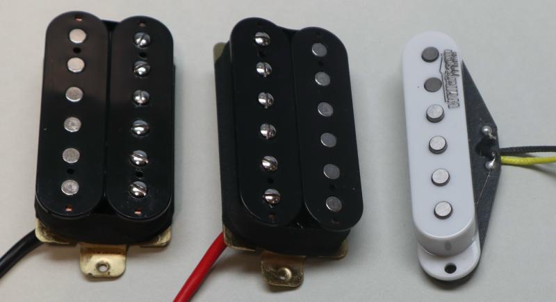
The pickups I tested are shown above. There are two humbuckers and one single-coil type. These are those I had available without stripping down my guitars, but they are representative of most of those you can buy. They are by no means 'high-end', but there's nothing to suggest that they are markedly different from any name-brand pickup. All use the same basic principles, and there's very little that can be done differently. I did not (and will not) cover different magnet materials. For a given field-strength, the material doesn't make any difference to the sound - unless it causes the physical form-factor (and therefore the inductance, capacitance or resistance) to change. The key point here is field-strength - that will affect performance (more output level with higher field strength and vice versa).
Ultimately, there is little to suggest that the sonic character of a particular pickup can't be re-created using EQ. As with most things in audio, there is an endless supply of myths about the alleged 'sound' of a particular style of pickup, even extending to the type of magnet, insulation material used on the coil winding wire and so on. Being (generally) passive devices, pickups have a limited range of characteristics - desirable or otherwise.
The simple fact in all of this is that almost no guitarist uses an amp without tone controls, and if it just takes an extra tweak of the treble or bass control to get the same sound from two different pickups, then any discussion of the pickup's 'tone' is irrelevant. There is no behaviour of any pickup that can't be re-created by EQ. If you find this comment challenging (or you don't believe it) then I suggest that you stop reading now.
One thing I will not do is use subjective terminology to describe any pickup. 'Smooth', 'silky', 'hot', 'bright', 'mellow' (etc.) terms mean different things to different people, and have no place in a technical article. I will only discuss frequency response, output level, and the physical characteristics of any pickup type. It's generally considered that anything much above 5kHz is unwanted, and if you look at the response of almost any guitar speaker, you'll see that most roll off above 5kHz. Of course, this is also something that can be controlled by EQ, but for the speakers it means that higher harmonics generated by 'overdrive' (distortion) are rolled off too. Anyone who's tried a guitar amp into hi-fi speakers will know that it sounds awful.
There are many different construction styles used. All involve a magnet (or a number of magnets) and one or more coils of fine wire. The wire gauge varies, but it's generally somewhere between 42 AWG (0.0635mm) and 44 AWG (0.0508mm) diameter (not including insulation). In some cases even thinner wire may be used, but it becomes very fragile once it's around 0.05mm diameter. As an example, I'll use 43 AWG (0.05588mm) diameter wire. This has an area of about 0.0025mm², and has a resistance of about 6.9Ω/ metre.
While the pickup area is small, the many turns (up to 10,000, but usually somewhat less) add up to a lot of wire. The resistance varies fairly widely depending on the manufacturer, but it can be anything up to 16kΩ. If you work that out, it can mean that there's up to 1km of wire on a typical pickup. The wire is delicate because it's so thin, and some pickups are potted in epoxy or wax to protect the coil and reduce microphony. The pickup should pick up the vibration of the strings, and nothing else.
Fig 1. shows the basics. The magnet may be at the base, or in some cases there's a separate magnet for each string. If an external metal case is provided, it must be brass and will typically be chrome-plated. Nickel shouldn't be used as it's magnetic, and that may cause unwanted microphony (causing pickup feedback), and it shunts some of the magnetic field so it doesn't interact with the strings. While many pickups use a plastic case, this should have a conductive coating inside to provide grounding. This minimises noise, but it's important that a close-coupled electrostatic shield doesn't form a shorted turn around the pickup. The alternative is to ensure that the outer windings are at ground, so they act as a shield for the remaining (inner) windings.
The magnet can be below the coil, or in some cases multiple cylindrical magnets are used, one for each string. In this case, a steel back-plate may be used that helps to increase the magnetic field strength. The output level is proportional to field strength. There's a limit though, as if it's too high it will deform the strings, although this is highly unlikely. No pickup I'm aware of will cause any significant static deflection. There must be some, but I'd defy anyone to measure it.
A humbucking pickup uses two coils, wound so that external fields cancel. The two coils are wound out-of-phase, and the magnets are reversed so the signal is reinforced. Most humbuckers are wired in series, but a parallel connection can also be used. This will sound different because the inductance is lower, so low frequencies may be somewhat weaker. Again, a bit of EQ will restore the response as required.
It's not possible to show all constructions, simply because there are so many. The principles are not changed though, because the essential physics apply regardless of the physical design. The magnetic polarity is arbitrary, and some brands will be the opposite of others. For a humbucker, the magnetic fields are opposite for each coil.
When a string vibrates within the magnetic field, it modulates the field and induces a current into the coil(s). The strings must be made from a magnetic material, either steel or nickel. Nickel is better because it doesn't rust, but there are many alloys that can be used as well. If you were to set up an electric guitar with nylon strings you'll be very disappointed.
The above is a combined drawing showing the magnetic interactions between the magnet, string and coil. The drawing is adapted from 'An Introduction to the Physics of Electric Guitar Pickups' by Spencer Rodgers of the Department of Physics and Astronomy, University of Kansas. When the string vibrates, it modulates the magnetic field in the polepiece, inducing a current into the coil. The modulation is very weak, so the coil needs a lot of turns to make the output voltage high enough to be useful. If the induced current is ±1μA, the output voltage will be ±1V into a 1MΩ load. The coil's resistance will reduce this a little.
The interactions between the pickup and strings are complex, but since they can't be altered without changing the pickup itself, this is of little consequence. As with everything audio-related, there are more myths than you can poke a stick at, and sorting fact from fiction isn't always easy.
Fig. 2.2 is adapted from the datasheet for 'Musiclily' pickups. These cost me the grand sum of AU$18.00 for the pair, but they appear to be very well made despite the low cost. The wiring schemes show how they are normally connected, but the windings can be separated, and can be used individually or in parallel (the default is series).
There are countless articles on-line that discuss pickups. Some are very technical, with countless formulae and measurements of response and phase, but much of this is irrelevant. The pickup's natural resonance is an important consideration, but there are few commercial designs where this is to no one's liking. People will have a preference of course, but simply adding a high-capacitance guitar lead can make far more difference than the choice of pickup.
I've shown the equivalent circuit for a standard (non-humbucking) pickup below. Like any coil, it has resistance, inductance and capacitance. The exact values vary widely, and those shown are an example only. Note that the output impedance of any pickup can never be lower than its DC resistance, and it will increase above the frequency where inductance starts to dominate. With the values shown, it doubles at 837Hz. A measurement frequency of 3kHz is generally fairly 'safe' (meaning that the error is acceptable).
While the parameters are actually largely irrelevant, it's instructive to see how they can be measured. Capacitance is the hardest, but even inductance is difficult to measure accurately. You may imagine that a good inductance meter will work, but the DC resistance is generally too high and the measurement will almost certainly be wrong. Most have limited frequencies for inductance measurements, and the test frequency must be below the pickup's resonant frequency (where the impedance is rising). I used 1kHz because I can only select in decade ranges - 100Hz is too low, and 10kHz is too high.

The pickup itself is a very simple circuit. It has DC resistance (DCR), inductance (L) and parallel capacitance (Cpar). For any given pickup, these are (more-or-less) fixed quantities, and they can't be changed easily (if at all). The external circuit comprises a 'tone' control and a volume control. I've not shown values for these, as they vary from one design to the next. The pots are usually between 250k and 1MΩ, with a 'tone' cap of between 10nF and 33nF. All guitars label the tone pot as such, but it's only a top-cut (treble reduction) control. In some cases it can create a (slight) resonant peak in the output when the 'tone' pot is at minimum resistance.
For example (and depending on the pickup itself and the value of the capacitor), when the 'tone' control is set for maximum treble cut, you may get a small peak before rolloff. At most, expect a few dB at somewhere between 400Hz and 1kHz. In some cases, this is an easy way to get a bit of extra treble, simply by adding a small cap directly in parallel with the pickup. For the circuit shown, adding 2.2nF gives a boost of about 8dB at 2.1kHz. Reduce the capacitance to increase the boost frequency. If you do this, the actual boost bay be less than I worked out, because of the loading of the pots and output cable. A pickup with an inductance of 3H and a 22nF 'tone' cap creates a resonant circuit at 620Hz with the pot at minimum resistance.
This can also explain why an electric guitar can sound very different with different cables. It's nothing to do with the quality of the cable, it's all about parallel capacitance changing the resonant frequency. The effect of the cable (kind of) goes away if the volume is reduced by turning down the control, but the added resistance and cable capacitance can affect high frequencies.
Ultimately, everything has an effect. Whether it's good or bad depends on what sound you're after. Most changes can be created (or defeated) with amplifier tone controls, but the response peak is different - it can be fairly sharp. Again, the Q ('quality factor') of the resonant peak will be different with different circumstances - especially the load impedance (volume, tone, cable and amplifier), but it will generally be at least 2-3 with a high impedance load (Q describes the bandwidth of a resonant peak).
The following graph was created using the values shown in Fig. 2.1, and is not intended to represent any particular pickup. However, all pickups will show a similar response because they have the same ingredients, albeit in differing amounts.
To measure the characteristics of a pickup, use a signal generator with an output of 1V, and feed that to the pickup via a 100kΩ resistor. Measure with a meter or oscilloscope with an input impedance of 10MΩ. You'll get a response similar to that shown in Fig. 2.2. The peak response is easier to see with a 1MΩ feed resistor. This gives a reasonable idea of the resonant frequency, and other characteristics can be derived from the readings you get. The minimum level is set by the coil DCR, and at very low frequencies, that forms a simple voltage divider along with the external 100k test resistor.
Using the pickups shown in Fig 1.2, I compiled the parameters of the coils. The results are tabulated below, and should be considered 'representative'. Other pickups will be very different.
| Parameter | DCR1 | DCR2 | DCRseries | Inductance¹ | Inductance² | Capacitance |
| Bridge | 7.75 k | 7.48 k | 15.23 k | 7.88 H | 3.53H | 47 pF |
| Neck | 4.08 k | 4.09 k | 8.17 k | 3.78 H | 2.15 H | 30 pF |
| Middle³ | 6.01 k | N/A | N/A | 2.59 H | 2.38 H | 122 pF |
Note that inductance¹ was measured with a high precision inductance meter, and inductance² is calculated using the formula shown below. Because capacitance cannot be isolated, it was calculated using the formula (also shown below). The reason the meter gives such a misleading reading is simply due to the DC resistance. The higher the resistance for a given inductance, the greater the error. The actual inductance is somewhere between the measured and calculated values. Note that the bridge pickup has many more turns to compensate for the lower level close to the bridge. This is because the string's vibration amplitude is far less at this point.
If these values are used with the simulator, the results are similar to the pickup's performance, but it's immediately apparent that the values aren't quite right. A high-precision vector analyser could be used to get a more accurate result, albeit with some effort. However, the values are largely irrelevant because you can't change them without rewinding the coils.
Of more direct importance is the minimum permissible load across the pickup. Ideally it will be as low as possible, as that means that the guitar cable has minimal interaction, but there's a limit. The bridge pickup needs a minimum load of around 330k, and anything less causes premature treble rolloff. The neck pickup has lower inductance and a much higher resonant frequency (I measured 19.5kHz). That means that the loading can be higher (lower resistance), but it's a compromise when the two pickups have different characteristics.
I tested another pickup (#3), a reasonable approximation of a Fender Stratocaster middle pickup. With this, I also measured the capacitance, which came in at 180pF. This particular pickup is very neatly layer-wound, which causes higher capacitance than 'jumble' or 'scatter' winding. With the latter types, the coil is wound without attempting to make the windings as neat as possible, which reduces the number of turns that will fit on the bobbin, but also reduces the capacitance.
Resistance is the most fundamental of all parameters. All 'real-world' conductors have resistance, and it always has an effect on the system. Resistance is easily measured with any multimeter. This is an unwanted characteristic, but it's unavoidable. Copper has resistance, and it will always be present. The resistance makes a direct measurement of inductance close to impossible, because a standard inductance meter can't separate the resistance and impedance. The resistance limits the output current, so most pickups require a high-impedance load.
The coil's resistance makes other measurements difficult, because it interferes with measurement systems. This is especially true for inductance, because the resistance is added to the inductive reactance, but the signal developed across resistance is 90° out-of-phase with that due to inductance. Due to the internal resistance, all high-impedance pickups have limits on the total load capacitance (discussed below).
Resistance measurements are not affected by inductance or capacitance, because they are performed using DC. There is one variable though - temperature. If a coil measures 6,000Ω at 20°C. that will rise to 6,342Ω at 35°C. Copper has a thermal coefficient of resistance (α) of +0.0038/°C. While this might seem important, it's not.
R = R × [1 + α × (T - T² )]
R = 6000 × [1 + 0.0038 × (35 - 20 )]
R = 6000 × 1.057 = 6342
The resistance increase seems as though it should make a difference, but compared to the other parameters it's benign. The difference can certainly be measured, but it won't be audible unless by some misfortune you manage to get the pickup much hotter than is typical for any venue. Even 35°C is pretty extreme, but it's within the range that's possible (however unlikely). It was different when all stage lighting used high-power incandescent lamps, but these are uncommon now.
Since a pickup has capacitance and inductance, it also has a resonant frequency determined by L and C (resistance doesn't affect the frequency, only the Q). The resonant frequency of any pickup can be reduced by adding external capacitance (from the tone control or guitar lead). The tone control can be set to maximum treble, and this (mostly) eliminates this from the equation, but cable capacitance is always an influence. There is no way to increase the resonant frequency, other than the use of 'trick' active circuitry. I don't know of any system that attempts this. It's certainly possible, but that does not mean that it's sensible.
Many subjective terms are used to describe the resonant frequency, so a low resonance (e.g. less than 1kHz) would typically be described as 'dark' or something similar. I dislike these terms because they only convey an opinion, not a fact. In general, a relatively high resonant frequency is preferred, and it can always be reduced by adding external capacitance. Ideally, it should be above 5kHz, as this is outside the frequency range that most guitarists prefer - particularly those who use amp overdrive. For classical playing, it might be desirable to reproduce frequencies up to 10kHz or more, and a low resonant frequency makes that hard to achieve.
In most cases, EQ can be used to restore the frequencies that are attenuated above resonance (see Fig. 2.0.2), however that comes with a noise penalty. If the resonant peak is particularly sharp it will boost a narrow band of frequencies, and it may not sound good. The easiest way to minimise the 'Q' (quality factor) of the resonance is to load the pickup with a lower than 'normal' resistance. For example, using a lower value volume pot may be able to eliminate the resonant peak (almost) entirely.
The graph was made using the values shown for the 'Stratocaster' middle pickup shown in Table 2.0.1. The resonance is very pronounced with the 'conventional' 1MΩ pot loading, but it all but disappears when the pickup is loaded with 100k. Note that above 10kHz, the response rolls off at 12dB/ octave, but at 10kHz the response is only 3dB down, so not much 'top boost' is needed if you want response to extend to 12kHz or so (about 6dB boost at 12kHz).
It's 'common wisdom' that all pots in electric guitars should be high-value (at least 220k, commonly 1MΩ). However, a high value means that cable capacitance has a much greater effect when the volume pot is used to reduce the level. As with all things in electronics, this is a compromise, and it will always cause tonal differences between different makes of guitar where the manufacturer has chosen what they consider to be the 'best' values to use.
While the inductance of the coil is one of its most important characteristics, you usually can't measure it properly with an inductance meter. Nor can you measure the distributed capacitance - it can't be separated into a measurable quantity because it is distributed. The only thing you can measure directly is the resistance, and any decent ohm meter will give you the correct answer.
Feed the pickup from a 1V source via a 100k resistor. Adjust the frequency to around 3kHz, and measure the voltage (e.g. 430mV). Since we used a 100k feed resistor, the effective impedance of the coil is 43k (close enough). This is inductive reactance, which can be converted to inductance (2.28H for this example).
L = XL / ( 2π x f )
L = 43k / ( 2π x 3k ) = 2.28H
This isn't exact, but it's more than close enough for what we need. It's not like it can be changed at will because you don't like the answer, as it comes with the selected design. If twin-coil humbucking pickups are able to be re-wired you may get some interesting changes, but usually at the expense of output level.
In some cases you will see graphs showing impedance and phase. I've elected not to include phase in any of the graphs shown here, because it's not as helpful as might be implied by others who've looked at pickups. At resonance, the phase angle is zero, because the inductive and capacitive components balance out (i.e. they cancel, leaving only resistance).
The capacitance of a pickup is distributed, as it acts between each individual turn and all others. It's a common engineering practice to use 'lumped' components, so the capacitance is shown as a single value, rather than a large number of individual parts. This does introduce an error, but it's generally within acceptable limits.
If the capacitance is too high, it causes a loss of treble. This is often made adjustable on the guitar, via the tone control. The guitar lead (and amplifier) add more capacitance, with the lead being the dominant factor. 'Zero Capacitance' preamps can be used (for an example see Project 214), which reduce the output impedance of the guitar so the lead's capacitance has no effect.
Once the inductance is known, you can then work out the approximate capacitance. Use the same 100k feed resistor, and adjust the frequency until the amplitude reaches a maximum. As simulated, this is at 7.4kHz. If it helps, 4 x π² is close enough to 40, and that will be more than accurate enough for any measurements you make.
C = 1 / ( 4 x π² x f² x L)
C = 1 / ( 4 x π² x 7.4k² x 2.28) = 203pF
This is also not exact, as the capacitor used in my simulation is actually 220pF. There's not really much to take away from these values, as they are fixed quantities that can't be changed. You only have control over the external circuit, which loads the pickup and changes its characteristics. The greatest influence (excluding the 'tone' control) is the cable. Depending on the type, this can add between 50 and 150pF/ metre. Low capacitance cables are preferred by many guitarists, as they are less likely to pull the resonant frequency of the pickup/ cable combination too low. This can be counteracted (to an extent) by heavier loading, meaning a lower parallel resistance. This reduces the level though, and makes the overall signal-to-noise ratio worse.
Most cable suppliers (i.e. they sell the cable and you make the lead) provide the capacitance per metre, but ready-made cables will typically not include this information. It is easily tested though, and many multimeters include capacitance measurements. The cable's inductance and resistance are generally immaterial, as they are too low to make a difference.
One cable characteristic is particularly important, and that's noise. The dielectric and construction of some cables leads to an issue called triboelectric noise, where moving the cable creates audible noise. Triboelectric effects are common, with one of the most commonly known being the electric charge built up as you walk across synthetic carpet with insulated shoes. In many cases it manifests as a static charge, but this is not the direct issue with cables but the effects are related. It's more commonly called 'cable noise' or 'handling noise', and it's present in all cables. It matters when it's audible, with some cables being particularly bad. A good quality cable will be almost silent, regardless of the amount of shaking or dragging it's subjected to. Triboelectric effects are exacerbated by high impedances, and the higher the impedance the more noise you'll get. A low source impedance pretty much eliminates the problem, but as seen above, most guitars are not low impedance. A low load impedance also works, but with most guitars this reduces the output level and messes up the response.
There are also low-impedance ('low Z') pickups, which are generally active. This means that they have an inbuilt or external amplifier designed to take the very low signal level from the pickup, amplify it, and present a low-impedance output. Cable capacitance is no longer an issue. In theory, there's not much difference, but a low Z pickup won't show a resonant peak within the audio band.
By using fewer turns, the internal capacitance is reduced dramatically, so while it will resonate, you can expect such resonance to be at 50kHz or more. There's also no reason that a transformer can't be used, a very common method used in microphones. That has been done by Gibson (and perhaps others). The transformer may pick up hum fields (as do the pickups), and may ultimately provide marginal real benefits.
A low impedance pickup can be designed to use a standard microphone preamp, but its output will be far too low to drive a standard guitar amplifier. If done this way it would typically be balanced, although that isn't strictly necessary. The idea that a balanced connection is required for microphones is incorrect, and an unbalanced connection will be just as resistant to noise pickup. There are undoubtedly countless people who will argue that this is wrong, but if they actually tested it they may be in for a surprise.
It's probably fair to say that everything affects the sound of guitar pickups. Some players might find a combination of guitar and lead that gives them the 'sound' they want, others will experiment by 'cable rolling' (changing cables and relying on auditory memory to decide which is 'better'). In some cases the results might be readily apparent, but this never should be taken to mean that you should spend $hundreds on a guitar lead. Most commercial leads will be alright, some will be very good, but you can always check the most important things with a multimeter with a capacitance scale, and by plugging the cable into a guitar amp without the guitar to listen for cable noise. Lower capacity will often correlate with lowest cable noise, but this is not a given.
Changing pickups will usually result in a different sound. It is very important not to confuse 'different' with 'better', as this is purely subjective. What sounds 'better' to one player may be deemed 'worse' to another, but the same differences can almost always be created with EQ. If you swap out a single-coil pickup for a humbucker, it will sound different. If a player doesn't like the sound, in some cases a tweak of the amp's tone controls may bring it back to something s/he does like, but that's never guaranteed. You could use a parametric EQ to ensure that the response of the two is identical, but subconscious bias may doom the project before you get that far.
In general, it's probably fair to say that guitarists often will hear differences that no one else can detect (and I have personal experience with this). Whether others can hear it or not is immaterial, because the player wants a particular sound for himself/ herself. Failure to recognise that simple fact can cause friction between players and technicians, but that's a philosophical discussion that doesn't belong here.
| Main Index Articles Index |