
|
| Elliott Sound Products | Opamp Selection |
 Main Index Articles Index Main Index Articles Index |
If I were to do a 'comparison' of opamps, it would not be what most people would expect. What you'll read here is a list of reasons that explain why 99% of so-called comparisons are best described as nonsense. There is no doubt that you need to select the right opamp for the task at hand, but it's based on science and engineering, not some random discussion about the 'sound'. There are differences, and I'd be the last person to deny that, but the important part is whether these are audible. For something to be declared audible, it either has to be clearly audible by an average listener, or determined by measurement that it should be audible to anyone with normal hearing. A loss of 0.1dB at 20kHz will go un-noticed by anyone (assuming that the circuit is otherwise well behaved). Claims to the contrary can be dismissed, because the vast majority of 'tests' are done where the tester knows which device is being auditioned and is subject to inevitable (albeit subconscious) bias.
People constantly claim that they can hear differences (often huge) that magically vanish when the listener is subjected to a blind (preferably double-blind) test. A double-blind test removes all bias, including subconscious cues that the person making the change may introduce. However, even a single-blind test is often sufficient to make all claimed differences disappear. The failure to evaluate properly is a major failing in the audiophile community, and the list of excuses they use to validate their 'findings' is all over the interwebs.
One thing that subjective 'reviews' invariably use is flowery language to describe differences. Response may be claimed to be 'soft', 'well controlled', 'tight', 'subdued' or 'harsh'. It may also be claimed that the highs are 'veiled', or that the midrange is 'strident'. These words are meaningless, and if one is describing the performance of an opamp (any opamp) they are just BS. These subjective 'reviews' aren't limited to opamps of course - valves (vacuum tubes), speaker cables, interconnects and even mains leads are regularly compared, and it's generally safe to conclude that all such comparisons are flawed. I would say that the vast majority are essentially a waste of electrons (or ink), and the so-called results can be dismissed without further thought.
As an example, I've seen many 'comparisons' where the bass response of opamps is discussed - often at some length. Without exception, the bass response of an opamp is defined by external parts, usually capacitors, and by definition all opamps extend their low-frequency performance to DC. This is where all opamps have their maximum gain, and therefore maximum feedback to ensure that the output is an accurate representation of the input (often amplified, but not always). As I pointed out in the article Designing With Opamps - Part 1, I have two 'rules' for opamps ...
#1 An opamp will attempt to make both inputs exactly the same voltage (via the negative feedback path)
#2 If it cannot do so, the output will assume the polarity of the most positive input
#1 applies in all linear circuits that are functioning as intended. #2 is important to remember, but it describes non-linear operation which is not used in the signal path. In reality, there are always small differences between the two inputs. These are created by input offset voltage (a datasheet parameter) and additional offsets created by unequal impedances at the inverting and non-inverting inputs.
Even if we aim to be able to reproduce high frequencies at full level (and destroying the tweeter in the process), we might aim for full output at 20kHz, even though it will never be achieved in use. A reasonable output level is 2.5V RMS (just over 7V peak-to-peak), and that's enough to drive most power amps to their maximum output power. Slew rate is easily worked out ...
Slew rate = 2π × f × VPeak
Even at 30kHz and with an amplitude of 2.5V RMS (3.54V peak), the slew rate is only 0.67V/μs. No opamp-based audio equipment will normally have to reproduce more than that - ever, so it's a fair and reasonable upper limit. In engineering, we usually like to add a safety margin, so it would be sensible to set the minimum acceptable slew rate to around 1V/μs. It's actually hard to find any audio opamp that slow, and as a minimum we'll be looking at around 5V/μs for even low-spec opamps that are suitable for audio use.
One reason that you may experience real differences is if the circuit and opamp are not suited to each other. If you were to try using a TL072 as a 600Ω line driver, then you can expect to be disappointed. Likewise, using an LM4562 (one of the best currently available) as a piezo preamp will lead to excessive noise, and a TL072 may beat it easily. This doesn't mean that one opamp is 'better' than another, just that it's more suitable for the application. This principle applies at many different levels, so 'comparing' opamps in anything other than a dedicated test jig is more likely to be pointless than useful.
If the opamps are tested in a unity gain circuit, be aware that some single opamps are internally compensated for some gain. The NE5534 is stable with a gain of three or more, but without an external compensation cap, it will oscillate in a unity gain circuit. I don't know how a 'reviewer' might characterise the oscillation, and it might even go un-noticed. However, you can be sure that the end result won't test well. Even the lack of a power supply bypass cap close to the opamp can cause oscillation in some cases, and it may not even be visible on the output when viewed with a scope. If you run tests on opamps, it's essential that you know what you're doing!
In some cases you may have a piece of kit that uses ±5V supplies, with opamps intended for that voltage. Almost all opamps will work (more or less) happily at that voltage, but you may find that the output swing is less than that from the original devices. This means that some opamps may sound worse because they are clipping at maximum level. This isn't a flaw in the opamp, it's an issue that the tester may not have even thought of! Likewise, there are some opamps (admittedly not many in through-hole packages) that are designed for a maximum supply voltage of perhaps ±5V. These will fail if your equipment uses ±15V supplies. A few designers have availed themselves of the ±20V supplies that can be used with NE5532/4 and a few others. This may destroy opamps that aren't designed to handle that voltage.
If you're using existing equipment and 'opamp rolling', you can't perform a blind test because you have to exchange the opamp(s) for each test. It can be done if you have two identical preamps (for example), and you can then use ABX testing. Interestingly, 99% of audible differences mysteriously vanish when ABX testing is used, and it's not because the switching creates mysterious masking effects. Of course, if you believe that this is untrue you can stop reading now, because you've already decided that I'm wrong.
I tested a number of devices (not all of those shown though) and in all cases the distortion was below my measurement limit (-100dBFS or 0.001% THD). There was one exception, an LM358, which is shown below (Fig. 2.3) just so you can see how bad it can be. It managed to get as high as 0.14% (-57dB), but I think that may be optimistic. The level was fairly high, and that tends to make the crossover distortion from this IC less obvious. The output stage is unbiased, so crossover distortion is inevitable, regardless of open loop gain. Distortion is created when an amplifier/ preamp is unable to reproduce the waveform accurately, and the root cause is non-linearity. All electronic parts are non-linear, with some worse than others. Resistors and capacitors (of the right type for the application) will normally have little effect.
When a waveform is modified by a non-linear element, new frequencies are generated. Harmonics are the most commonly examined, but intermodulation distortion is worse. Both types of distortion exist simultaneously, but you won't see intermodulation with a single tone. Intermod creates (or may create) sum and difference frequencies (i.e. f1 + f1 and f1 - f1). In turn, these new frequencies generate even more additional frequencies. This leads to a great many new frequencies that didn't exist in the original signal.
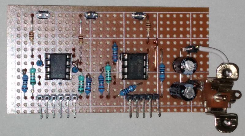
The board is designed to use a single supply, with a 'rail splitter' used to provide about ±6V from a Li-Ion battery pack. This was used to eliminate any power supply noise which will degrade the measurements. The first socket is for dual opamps, with both sections populated to allow crosstalk measurements. The second socket is for a single opamp. The opamps are all configured for a gain of 3.2 (just over 10dB) so that compensation isn't needed for NE5534 opamps, which require a compensation cap if used with a gain less than three. The schematic is shown next.
The schematic is very straightforward. There are supply bypass caps for each opamp socket (not shown above for clarity). These are standard 100nF, 50V X7R multilayer ceramics. There are no input, output or feedback caps used to allow for DC offset tests. The worst-case offset was with an NE5534, at about 10mV. This is of no consequence of course, as in a real circuit it's removed with a capacitor. The offset with bipolar opamps is made worse because the input resistor is 10k, and even the NE5534 has less than 2mV when the input is grounded with a 100Ω resistor. 100Ω output resistors are used to ensure that fast opamps don't oscillate when a shielded cable is attached.
I did not include a compensation capacitor, because it can cause problems with an opamp that doesn't need one. The pinouts for dual opamps are standardised, but with single opamps, the extra 3 pins can be used differently depending on the opamp. Pins 1 & 8 are often used for adjusting DC offset, but Pin 8 may also be used for compensation (NE5534). If an opamp that doesn't need compensation is used with a compensation cap connected between Pins 8 and 5, the results are unpredictable.
Needless to say, every opamp I tested was flat to DC, taking any DC offset into consideration. No one would expect it to be any different of course. Response was tested to the upper limit of each opamp, with an output level of 2V RMS, and most managed 100kHz easily (the μA741 was well down at 100kHz as you'd expect). The LM4562 measured flat to 500kHz - very impressive but not even remotely useful for audio.
Measuring frequency response isn't useful overall, because all ('audio grade') opamps were dead flat from DC to at least 100kHz (±0.1dB) with the 10dB gain circuit I used. A graph showing a whole bunch of straight lines is of little use to anyone. Ultimately, everything is subject to the laws of physics, from bits of wire to complex computer ICs. Despite the longing by some for it to be otherwise, these laws reign supreme over everything we do.
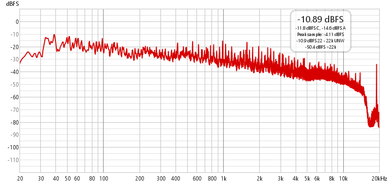
The first measurement is the spectrum of a variety of music and speech captured from FM radio. You can see that everything is rolled off above 16kHz, and the 19kHz stereo pilot tone is seen to the far right of the graph. This is used to extract the 38kHz stereo sub-carrier, comprised of the L-R signal. This is the peak amplitude taken over a 20 minute period. The general roll-off of high frequencies is quite obvious, and the graph shows ~20dB roll-off from 1kHz to 16kHz, or 3dB/ octave.
I took measurements of quite a few opamps, and most were below my measurement threshold. The lower limit of what I can measure (using the Project 232 Distortion Measurement System) is -120dB, and with a signal level of about -20dB the lower limit is 0.001%.
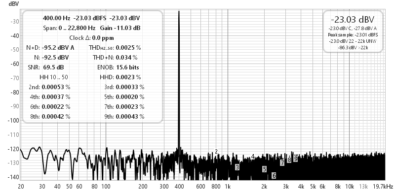
The harmonics are below the noise, so it can be inferred that not only does the RC4580 add little noise, but its distortion is negligible. A lowly TL072 looks much the same, as does an NE5532 or NE5534. A μA741 doesn't fare so well, with the 2nd harmonic at -116dB and clearly visible. Since we won't use the 741 for audio, this is of no consequence. At low levels (no more than 1V peak), a 4580 can drive a load as low as 200Ω without showing increased distortion. By way of demonstration, the next graph shows an LM358 opamp, showing why they are no good for audio.
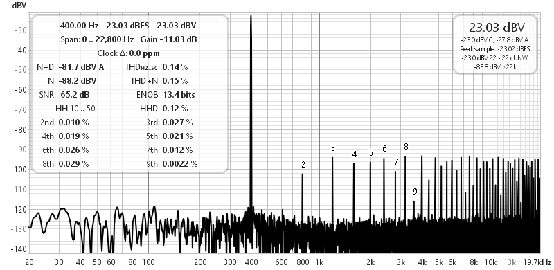
The harmonics extend to well beyond 20kHz, and it sounds awful. It's not obvious, but distortion gets worse at lower levels, because it's crossover distortion created by an un-biased output stage. For many mundane tasks (metering amplifiers or signal detectors for example) we don't care, because the opamp isn't in the signal path so any distortion is not reproduced along with the audio. It is possible for force Class-A operation in the output stage with a current sink (typically a resistor from the output to the negative supply), but why would you bother?
While I could show a graph for every opamp I tested, that would be pointless, because they were all very similar in the tests I ran, and without an Audio Precision test set (or something equally advanced) I measured all to have distortion below the noise floor. While REW (Room EQ Wizard) is very capable, it doesn't match dedicated hardware and software once distortion is below audibility. That's the crucial point here - if distortion is likely to be audible, then we need to know about it.
Once we approach the limits of audibility, anything that may be added is pretty much immaterial, because we can't hear it. It's worth noting that if you operate your stereo at 100dB SPL and distortion products are at -100dB relative to full output, that puts them at 0dB SPL, the lower limit of audibility. Anyone with a room that has a residual of 20dB SPL is very fortunate indeed, so the highest distortion products are 20dB below the room noise.
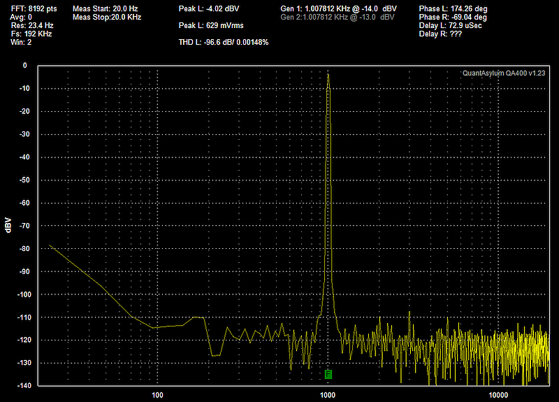
I also revisited my (now rather old) Quantasylum QA400 unit (which needs a Win7 machine to run), and it reports the distortion as 0.0015%. While it was running, I also verified channel separation for the RC4580 which was in the other socket (and showed the same distortion). Separation measured over 100dB, despite the use of Veroboard and flying test leads for the test jig. The limits are in the test equipment, not the opamps. I daresay that if an Audio Precision test set were to magically appear in my workshop I'd be able to get greater accuracy, but it's a moot point because the distortion is way below anyone's hearing threshold.
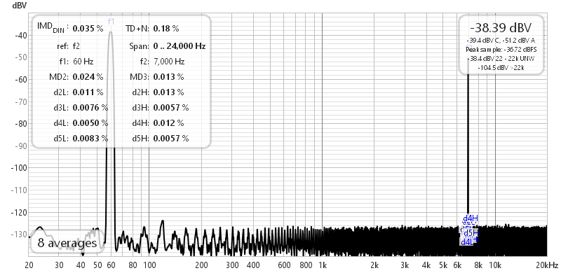
The intermodulation distortion (IMD) measurement was taken using a different circuit, with the gain configured for 10 (20dB), with a very low resistance feedback network. The two standard frequencies are 60Hz and 7kHz, and intermod is shown by sidebands on the 7kHz signal. With zero IMD the 7kHz signal stands alone, but if it's amplitude modulated by the 60Hz signal, you'll see frequencies of 6.88kHz and 7.12kHz, along with additional frequencies spaced at ±60Hz or 120Hz intervals. The frequencies depend on whether the distortion is symmetrical or asymmetrical. For a complete discussion of IMD and how it's measured, see Intermodulation Distortion (IMD).
One of the best tools for direct comparisons is a 'null test'. In this test, the outputs of two devices are subtracted and any difference shows up as a non-zero output. If the two devices are identical (and they can be opamps, power amps, cables, or anything else you wish to compare), the final output is zero. Two equal and opposite voltages cancel, and the null test is incredibly sensitive. This is both a strength and a weakness, because the resolution can be in the order of microvolts. A tiny phase-shift (completely inaudible) can result in a significant output voltage.
A mere 1° phase difference with two 1V (peak) signals will result in an output of about 17.5mV peak, a rejection of only 35dB where we would expect at least 100dB (a peak output of 10μV). Correcting for phase differences is difficult, so the null test is very hard to get right. As pointed out in the article [4] by Ethan Winer, a phase shift of only 0.006° is enough to reduce the null to -80dB, and making such a tiny correction involves using small trimmer capacitors. You also need to use 'premium' opamps if you use an external nulling circuit. An alternative is to use a 'reference' opamp and a 'test' opamp, wired so that one is inverting and the other non-inverting. However, this means that the two opamps are functioning with different noise gains because of the different topologies. This makes a null test far more difficult and less predictable. A separate subtraction stage is better, so that the two 'test' opamps operate with identical conditions. The circuit shows 'DUT' (device under test) and 'REF' (reference) opamps. The subtraction stage (U3) has to be a very high quality opamp for best results.
The circuit shown above is a fairly simple way to perform a direct comparison. The opamps are operated with a gain of 10dB (near enough), so you get an idea of 'real life' performance. The positioning and values for the phase compensation networks (VR1a/b and C1a/b) need to be determined empirically, as they will be different with different opamps. A reasonable starting point would be to use 2k multi-turn trimpots and 22pF (maximum) variable trim capacitors. The (phase) compensation parts are shown in grey, and are indicated as 'SoT' (select on test). Each opamp requires a bypass capacitor across the supply pins. These aren't shown for clarity.
In some cases you will need to add capacitance, and one of the networks may need to be disconnected. It should be possible to get at least 80dB rejection up to 20kHz, but the settings of the trimpots and trim-caps are extremely sensitive. The values shown are designed to compare a pair of opamps (singles are indicated by the pinouts, but dual types are tested the same way). Each opamp needs a bypass cap between the supply pins.
The balancing networks are extremely sensitive, so much so that a change of 1Ω can make a big difference. Even using 0.1% resistors throughout will still not be close enough, so trimpots and trim capacitor(s) are essential. There is no way to know in advance the amount of compensation needed, nor where it should be. Null testing is very powerful, and can resolve differences that can't be measured any other way. However, it it's not adjusted perfectly to match amplitude and phase, expect problems.
In a simulation, but without too much mucking around, I was able to get a difference signal at -85dB, and while this is pretty good, it's not really good enough! With two identical opamps the difference was -153dB. It's unlikely that you'll be able to do much better. Loading one opamp with 10k reduced that to -88dB, but you'd need extraordinarily good equipment to measure the change due to the added load. From the simulation, it appears to be an amplitude change of just under 80nV with 5k vs. 10k load. Good luck measuring that without the best equipment available!
A couple of pF stray capacitance and (say) 100GΩ leakage resistance will make a big difference in the final measurement, which gives you some idea of just how sensitive a null test can be. At the end of your testing, how will you know which opamp was 'better'. Anything that results in a difference of -100dB or more is so far below audibility that it would be silly to worry about it.
There are quite a few people who have gone to extraordinary lengths to test opamps for audio. Many of these are subjective only, and can be discounted without a second thought. Others have been much more thorough, but it may be quite hard to see anything meaningful in the results. There's a definite limit to how much time is spent on this - one could keep going for months with good enough test gear, and the end result would be a very large number of graphs that few people will look at anyway.
The devices I'd normally consider are as follows (ranked by input voltage noise). The AD797 is out of contention for anything other than extreme (and costly) applications due to its rather exorbitant cost. A cheaper alternative is the LT1115 (and its ilk - there are a few devices in the LT11xx series). Of the others, I have used them all - including the LM833 (except for OP1612 and OP275). The 833 is easily beaten by the far cheaper MC/RC4580 which I use quite a lot for tests and general experimentation.
Note that I have not considered offset voltage or current, drift or current noise in the following table. Only voltage noise is included, as this is dominant in most audio circuits. A 1kΩ ideal resistor has a noise voltage of 4nV/√Hz, and somewhere around 1k is a fair estimate of the average output impedance of typical signal sources.
The abridged specs shown are 'typical' as shown in the datasheet for each opamp. Do not use the table to make a final selection - you must refer to the datasheet so you know how the manufacturer recommends that the device be used, and to see the other parameters. For example, PSRR (power supply rejection ratio) isn't shown, and nor are input/ output resistance, bias current, DC offset, etc., etc. Just as the figures are 'typical', so is the general test circuit. If you stray too far from the Fig. 1.2 circuit, you may need to change your expectations.
| Opamp | Gain BW | Slew Rate | Gain | Noise nV/√Hz | THD | |
| AD797 | 110 MHz | 20 V/ μs | 10 kV/ mV | 140 dB | 0.9 | 0.001% |
| LT1115 | 70 MHz | 15 V/ μs | 15 kV/ mV | 143 dB | 0.9 | 0.002% |
| OPA1612 | 40 MHz | 27 V/ μs | 3.16 kV/ mV | 130 dB | 1.1 | 0.000015% |
| LM4562 | 55 MHz | 20 V/ μs | 10 kV/ mV | 140 dB | 2.7 | 0.00003% |
| NJM2068 | 27 MHz | 6 V/ μs | 1 kV/ mV | 120 dB | 3.2 | 0.001% |
| NE5534 | 10 MHz | 13 V/ μs | 100 V/ mV | 100 dB | 3.5 | 0.002% |
| RC4580 | 15 MHz | 5 V/ μs | 316 V/ mV | 110 dB | 3.5 | 0.0005% |
| LM833 | 9 MHz | 7 V/ μs | 316 V/ mV | 110 dB | 4.5 | 0.002% |
| NE5532 | 10 MHz | 9 V/ μs | 100 V/ mV | 100 dB | 5 | NS (0.002%) |
| OP275 | 9 MHz | 22 V/ μs | 200 V/ mV | 106 dB | 6 | 0.0006% |
| OPA2134 | 8 MHz | 10 V/μs | 1 kV/ mV | 120 dB | 8 | 0.00008% |
| RC4558 | 5.5 MHz | 2.2 V/ μs | 200 V/ mV | 106 dB | 12 | 0.008% |
| TL072 | 3 MHz | 13 V/ μs | 200 V/ mV | 106 dB | 18 | 0.003% |
| μA741 | 1 MHz | 0.5 V/ μs | 200 V/ mV | 106 dB | 23 | 0.06% |
The devices listed are just a small sample of those available, and the figures are 'typical' as shown in the datasheet. The first and last devices are generally excluded, the first for price (~AU$35 each) and the last because it's a poor choice for audio. However (many years ago), the μA741 was used in countless audio projects because it was the first affordable opamp that was readily available. Even today you'll find many audio circuits on-line that use the μA741 (or LM741 which is identical). The only devices I've not used are the OP1612 and OP275. Everything else (along with a number of others) have been tried at one time or another during my almost 60 years working with audio circuitry.
While I have included the LM833, it's far from being a favourite of mine. In fact, I don't even have any in stock because for low cost applications I'd much rather used an MC/RC4580. These are dirt-cheap but surprisingly well performing opamps, and they beat the LM833 in almost all respects. I did not include the LM358, because although it's a very handy IC, it's simply not suited for audio. You can force the output into Class-A operation (at least for medium-high load impedances), but there are far better devices that are intended for audio use. The ultra-low cost RC4558 is included because it's long been a favourite in guitar amps and pedals.
While the JFET input TL072 seems very noisy compared to the others, if it's used with a high impedance source it will outperform the bipolar input opamps (with the possible exception of the LM4562). TL072 opamps remain a popular choice in many guitar amps, active filters, etc. While this family of opamps is generally scorned by 'purists', the chances of anyone picking it from the others in a blind test is remote, provided it's used with enough level to ensure than noise isn't intrusive.
While 0.002% THD (total harmonic distortion plus noise) doesn't look wonderful, it's well below audibility. Remember that NE5532 opamps were the defacto standard for mixing desks made from the later 1970s until fairly recently (and they are still an excellent choice). That means that almost any music you can think of has already passed through perhaps 100 or more NE5532 opamps during recording, mixing, mastering, etc., so it's silly to imagine that one or two of them in a preamp will somehow 'ruin' your listening pleasure.
The OP275 is claimed to be specifically for audio, but it doesn't come close to the LM4562 in any parameter except slew rate. This is of no consequence, as even a 741 could provide ~3V RMS at 20kHz. The OP275 is an expensive IC that (IMO) fails to meet its objectives. Expect to see people sing its virtues for subjective tests, mainly because we are told (in the datasheet) that it's 'designed for audio'.
You will almost invariably find that different authors of opamp comparisons will arrive at different levels of distortion, particularly for the NE5532/4. As one of the most popular devices for such a long time, it has more than its fair share of lovers and haters. Douglas Self measured distortion at less than 0.0005% at all frequencies below 10kHz with a 5V RMS output signal (±18V supplies).
The selection of an opamp depends on many factors. An opamp suitable for amplifying the output of an electric guitar will be very different from one intended to be used as an I/V (current-to-voltage) converter following a DAC (digital to analogue converter). The latter needs to be much faster than expected, because there will be high-frequency noise from the digital circuitry that the opamp is expected to be able to handle without becoming non-linear. That means it's probably going to be a premium device, designed for this application. That does not mean it will sound 'better' in other purely analogue circuitry.
If you need to amplify a low-level DC signal such as that from a current shunt, you have to take special precautions to minimise DC offset. This is obviously not an audio application, and the defining opamp parameters will be very different from those expected of audio devices. You have to account for drift with temperature and age, and a very stable DC offset is required. DC amplification is common in instrumentation, but is not a requirement for audio, since audio does not contain any DC.
The possible exception is a DC servo to ensure a power amp (for example) maintains a very low DC offset. The idea of a servo is not (or should not) be to eliminate capacitors from the signal path, as a cap is the only safeguard against a faulty preamp sending DC to the power amp and destroying speakers. Yes, you can use a DC protection circuit, but that may not detect small (but sound-damaging) DC in speaker voicecoils. Not enough to cause damage, but enough to ruin speaker linearity. If your speakers use cored inductors, the DC may cause partial saturation, creating distortion. The idea that a DC servo is 'better' than capacitors is covered in detail in the article DC Servos - Tips, Traps & Applications. Contrary to popular belief in some circles, they are not a panacea, and can even do more harm than good if not implemented properly.
The selection criteria are (or should be) based on engineering principles, with decisions made considering the type of circuit, its required speed, drive capability (load impedance), signal level, noise and expected build cost. Allowed supply voltages and even package style will eliminate some candidates, as will supply chain disruptions in some cases. Spurious claims found on the interwebs for 'musicality' or 'superior sound' do not form part of the selection process! For any given requirement, there may easily be 10 or more opamps that would suit, so you'd likely choose one that you've used before. For exotic designs (precision circuits, DC amps, etc.) the choice is harder, because you have to look at parameters that you don't need to worry about for audio.
In some cases you may have to consider the common-mode voltage (i.e. the signal common to both inputs), or you might have a need for rail-to-rail inputs or outputs. It's worth noting that no opamp can have a 'true' R-R output, because there must always be a small residual voltage (with an 'normal' opamp that's ±1.5V to ±2.5V depending on load current). Some opamps allow the inputs to be operated below the negative supply voltage/ ground by around -500mV or so. These requirements are usually not a consideration for audio circuits.
My opamp selection criteria are pretty straightforward. If I'm testing an audio circuit I'll often use whatever I have closest - that could be a TL072, RC4580 or (less likely for basic testing) an NE5532. If the circuit is designed for particularly low noise, then I may use both opamps in an NE5532 in parallel, or choose something more exotic. I know from measurements that it doesn't matter which opamp I use, it will probably be alright, but be aware of the load impedance limits for the TL072 (and some others). If you need to drive a 600Ω load, then you're going to use an NE5532/4, LM4562, OPA2134 or other opamp designed for the purpose. If you have a high impedance source, then choose a JFET opamp. For most medium impedance circuitry used for audio, it's hard to go wrong with an LM4562, as one of the best opamps available.
Anyone who claims that you need a discrete opamp module and that spending less than perhaps €35 (about AU$60) up to €150 (nearly AU$250) for a dual discrete opamp will give unsatisfactory (for whatever reason) results has a hidden agenda or is hopelessly misguided. The hidden agenda? Quite likely earning a commission on the sale of highly overpriced audiophoolery. This is bullshit! While countless claims are made for the alleged 'superiority' of very costly discrete designs, if there is no audible benefit (blind test!) then they are a waste of money. I'm sure that they typically perform well, and I'm equally sure that they will never be subjected to a proper blind test. Being discrete, they often can deliver much higher current than an IC, so the exact application has to be considered. For example, it may be possible to use one as a headphone amp with no outboard driver transistors.
Discrete opamps generally have very good specs, but they are seriously expensive, and very rarely (if ever) needed. I'd classify them as 'vanity' products - not required, but a demonstration of one's wealth. For anyone who wants to experiment with a simple discrete opamp, try the Project 37 design. It will not (and was never intended to) equal an IC opamp, but it's fun to build and works very well considering its simplicity.
Of course, there are many other opamps that are (or claim to be) ideal or even specifically for audio. Some are SMD only, and some of those use very DIY unfriendly leadless packages. The ones I listed are all available as standard 8-pin DIP ICs, allowing easy comparisons if you wish to do so. Remember though, if a listening test is other than double-blind it's useless, because psychological influences cannot be eliminated when you know what's being tested. I suspect that more than a few people think they are unaffected by such bias, but the fact is that no one is immune. That includes those who already know that they aren't immune, but imagine that they can somehow mentally compensate. I know for a fact that I'm influenced one way or another, and that includes believing that there is no difference even if it does exist!
Ignore subconscious bias at your peril. It is a part of the way we humans are built, and you cannot 'turn it off'. It works when we compare anything, not just audio. Measurements are your friend, because they help you to understand what a component is doing. No one would claim (or one hopes this is true) that using a meter to check a resistor's value was less revealing than how it sounds, yet you are often expected to believe reviewers who tell you that 'this' opamp is far superior to 'that' one for reasons they cannot explain.
I don't play this silly game, and I suggest that you don't either. The specifications and measurements matter, someone's opinion doesn't.
When you see phrases such as those below (and they are adapted from 'real' reviewer's comments on various opamps), you can be sure that there's only subjective bullshit and zero science. The words used have no meaning in engineering. Had the opamps being compared been tested properly (especially THD+noise and frequency response), I would expect that no significant measurable difference will be found, with all 'effects' below audibility.
There is a cohort of audiophiles who seem to think that some opamps have 'better' bass than others, but this is a laughable idea since all have well-controlled response right to DC. The bass response of a circuit is determined by passive components (almost always capacitors), and the opamp has (and can have) no effect whatsoever. All opamps have maximum possible gain (and therefore maximum feedback) at DC and up to 10-100Hz (device dependent), and even at 100Hz there is more than enough gain to ensure that gain linearity is close to perfect.
Phrases to Look Out For...
The sound is congested, with a dry 'mechanical' sound in which music doesn’t 'flow'.
A good all-rounder with a nice stage and resolution.
Emphasised bass more than 'x', with perhaps a bit more lower midrange presence and slightly less upper midrange.
Nicely balanced but lack dynamics.
More polite and less fatiguing.
A bit louder with more innate gain.
Detail is being shoved in your face at times, which leads to fatigue.
Well balanced & non-fatiguing.
Less forward than 'x', with a wider stage perception.
Bass is slightly biased towards sub bass rather than midbass, and a slight absence of midbass warmth.
Flatter than 'x' and the sound stage was not as spacious, with a more pronounced blobby left/middle/right perception rather than the stage feeling like a unified 3D space.
There is no known measurement for 'sound stage' (for example). It's purely subjective, and is something one normally associates with speakers, not opamps! All opamps have crosstalk that's well below audibility in anything other than poorly designed electronics. The BBC demonstrated long ago that provided crosstalk is below -20dB or so, anything more is superfluous. No one would accept 20dB of channel separation today, and there isn't a dual opamp ever made that's less than 80dB (at least 100dB is common). As for terms like 'polite' and 'blobby', I cannot imagine how these could translate to any engineering terms. As for any opamp sounding different in the bass region, that's just nonsense. Bass response is determined solely by external components, and changing the opamp will never affect the bass unless a misguided designer has made an incredibly poor choice of external parts. I can't think of how this could be achieved.
It's perfectly alright to have a 'favourite' opamp, provided there's some technical reason for it. I have several 'favourites', and not one is determined by its 'sound'. The list of opamps shown in Table 3.1 should give you an idea of my preferred devices - it's almost all of them, chosen for the specific results I'm after. Of those shown, I haven't used the OP275, I dislike the sometimes marginal stability of the LM833, and the μA741 is never used for audio in my workshop (it was different 60 years ago). The AD797 is so outrageously expensive that it's been used in only one project - Project 187 (Moving Coil Phono Head Amplifier).
In general, almost all opamps should sound the same in a blind test with medium levels (100mV or more) and a gain of 10dB or less. Any application that's expected to have very high gain and/or low noise will require an opamp designed for the intended usage. Ditto for opamps that are used with DACs or anywhere else they have to contend with a combination of high frequencies and audio. You can never just decide on an opamp and use it for everything - life doesn't work that way. 10dB of gain may not sound like much, but it's often as much as you need for a preamp stage. Two stages with 10dB of gain will bring the input level up to something 'reasonable', allowing for the losses in volume and balance (if used) controls. Few power amplifiers need more than around +4dBV (about 1.58V RMS) input for full power, so if your preamp can manage 5-6V RMS it will drive any amplifier ever made. This is easily achieved even with ±12V supplies although ±15V is usually preferred.
| Main Index Articles Index |