
|
|
| Elliott Sound Products | Current Transformers |

 Main Index
Articles Index Main Index
Articles Index
|
For those brave souls who have ploughed their way through the first section - I commend you! As you have discovered, transformers are not simple after all, but they are probably far more versatile than you ever imagined. They are, however, real world devices, and as such are prey to the failings of all real components - they are imperfect.
This section will concentrate a little more on the losses and calculations involved in transformer design, as well as explain in more detail where different core styles are to be preferred over others. Again, it is impossible to cover all the possibilities, but the information here will get you well on your way to a full understanding of the subject.
The first topic may seem obvious, but based on the e-mails I get, this is not the case. Transformers can have multiple windings, and these can be on the primary or secondary. Windings can be interconnected to do exciting and different things, but from a safety perspective it is imperative that primary and secondary windings are kept segregated.
There are several references to 'shorted turns' within this article. If any two turns of a winding short to each other, the current flow is limited only by the DC resistance of the shorted section of the winding. The current flow can be enormous, and with even one shorted turn, the transformer is no longer serviceable and must be discarded or rewound. No shield or other conductive material may be wrapped around the winding and joined, as this creates a shorted turn capable of possibly hundreds of amperes. The exception to this is the magnetic shield sometimes used with E-I laminated transformers, but this is wrapped around the entire transformer (outside the core), and is not considered as a 'turn' as it is not in the winding window with the primary and secondary.
It is also worth noting that a transformer behaves quite differently depending upon whether it is driven from a voltage source (i.e. very low impedance, such as a transistor amp or the mains) or a current source or intermediate impedance. This will be covered in a little more detail further on in this article.
One thing that you need to keep in mind - always ...
This important point is especially relevant to current transformers, and the result can be seen in Fig. 1.3. CTs must always have the burden connected, as the results otherwise are as unpredictable as they can be dangerous - especially when high current is being measured or monitored. There's no reason that the burden can't be reduced, but if it's increased you'll get saturation at a lower then expected current.
Many hobbyists (and more than enough professionals as well) make horrible errors with current transformers. The biggest mistake is a poor choice of burden resistance (usually too high), or being silly and/ or using a precision rectifier circuit when all that's needed is an indication (i.e. the exact current is immaterial). For detection (as opposed to measurement), the amount of current is of no interest, but we may want to detect it if it exceeds (say) 100mA but ignore it if less than that. This is easily done, and requires little or no special circuitry.
I've seen some very bizarre circuitry in place of a simple burden resistor, and I've done so myself. However, the loading should ideally be symmetrical, and the output voltage kept reasonably low. It's all too easy to get as much as ±80V (see Fig 1.3), which will not be enjoyed by any following silicon. That's enough to kill the input circuit of an opamp or an ADC input to a microcontroller. Perhaps surprisingly, if the output of a CT is applied directly to a bridge rectifier with the burden resistor after the bridge, you can get an acceptably accurate output as long as the current is not less than 10% of the rated CT current.
It's important to realise that the winding resistance of the CT's secondary has to be considered. It may look as if it forms a voltage divider with the burden resistor, but that ignores the fact that the output is current and high impedance. In theory, the winding resistance makes no difference, but reality is cruel. The measured output will always be just a little less than the actual. This is easily changed by adding a small amount to the burden, so a 100Ω burden may be increased to perhaps 110Ω to get better than 1% accuracy. The level can also be made up with some gain from an opamp where particularly accurate measurements are needed. One way around this is to use an opamp as a current to voltage converter (I/V), covered below. This is not without some difficulties though.
Of all transformers, one of the least understood (or most misunderstood) is the current transformer (CT). While these seem initially to defy the general rules of transformers, they actually do no such thing. Should you search the Net, you can find a great deal of information, but much of it is extremely technical (excessively so for a general understanding) or in some cases, very misleading. Some of it is just plain wrong. The information below is verified by testing and/or simulation. Note that I have not attempted to look closely at phase angles or vector/ phasor diagrams. These may be interesting, but are irrelevant to this explanation because they only become significant when more complex measurements are needed and/or absolute phase becomes important.
Where an ideal voltage transformer has a very low output impedance and behaves as a voltage source, an ideal current transformer has a very high output impedance, so acts as a current source. Within reason, the secondary current is unaffected by the load resistance (a low to very low resistance is preferred). The load connected across the secondary is known as the burden. This may be a resistor, an ammeter, or other equipment that is designed to apply the correct load to the CT's secondary circuit. The term 'burden' is used to differentiate it from the 'load' which is assumed to be the load (e.g. motor) on the (usually) single-turn primary of the current transformer.
Current transformers are used to measure the current in a conductor, and most commonly use only a single cable or bus bar passing through the centre of a toroid. The secondary winding is conventional (wound around the core in the usual manner), and is specified by the turns ratio, rather than as a specific voltage as seen with conventional voltage transformer specifications. Indeed, voltage is not the preferred output from a CT - because it's a current transformer, we expect to monitor output current. The burden resistor (where used) acts as a current to voltage converter, and the lower the value the better.
Traditional current transformers (as used in switchboards and power stations/substations for example) use laminated transformer steel cores, have limited bandwidth, and are generally designed to provide an output of 5A to drive a moving-iron meter movement. These may be thought to be 'true' current transformers, in that there is rarely any requirement to measure a voltage across a defined resistance. However, any load (meter or other indicating device) will always have some resistance, so there will always be a voltage developed across the burden - intentional or otherwise.
The ratio for these 5A secondary transformers is usually given as 1000:5 for example - 1,000A input drives a 5A meter to full scale. They are still surprisingly common, because most modern indicators and protective devices (including fully electronic types) are still designed for a 5A input (this is an industry standard for mains power monitoring). The typical burden for a 5A output is 0.2 ohm, so 1V will be developed across the burden at full current. Note that wiring resistance between the CT and the instrument increases the effective value of the burden, and this may cause inaccuracies if the cable is not sized appropriately.
For workshop use, we use electronics for most measurements (digital readouts for example), and these require a voltage input. This is obtained by monitoring the voltage across a defined resistance value, and operating secondary current is generally very low - certainly no more than 1A, but more typically less than 100mA. A current transformer with a ratio of 1000:1 will give an output current of 1mA/A of input current. If high currents need to be measured, the ratio may be higher or the burden lower - if 1,000A needs to be measured with output current appropriate for modern electronics, the burden could be reduced to 1 ohm, so 1,000A will give an output of 1A - 1V across 1 ohm. However, it is important that the transformer is actually rated for 1,000A - you can't expect a 10A CT to remain linear if both the primary and secondary current is 100 times greater than it's supposed to be. Not only will the core saturate, but the secondary winding may burn out because of excessive dissipation.
Naturally, one can still use an industry standard 5A current transformer, even to feed a modern true RMS meter. As noted above, the typical burden is 0.2 ohm, 1V will be developed across it at full current, and the burden (if purely resistive) will dissipate 5W. These figures are all within the boundaries of normal low-power electronic equipment. However, few of us need to be able to measure 1,000A in our workshops unless we happen to be building a welder. Most loads are less demanding, and call for a current transformer designed for lower output current.
We know that to measure current we can simply apply Ohm's law - include a series resistor and measure the voltage across it. However that means that there will be a voltage dropped across the resistor, and it will dissipate power. This becomes irksome in an industrial application, where the current we wish to monitor may be thousands of amps! There is also a small matter of safety - a current transformer provides an important safety barrier, in that the secondary is completely isolated from the single turn primary. As with all transformers, current transformers are only usable with AC.
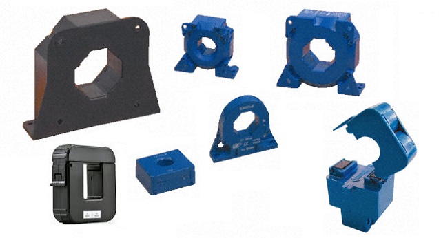
Figure 1.1 - A Selection Of Typical Current Transformers
The CTs shown in Figure 17.1 are but a tiny sample - there are hundreds of different styles available, with current ratings from a few amps to thousands of amps, output currents of a few milliamps up to 5A, and designed for 50/60Hz up to hundreds of kHz (sometimes used in large switchmode power supplies). It is far more important to understand the general concepts - appearance and the finer points of the design are unimportant as long as it works as intended. Current transformers are based on ampere-turns as are all transformers, but it's not considered an especially important factor for a conventional voltage tranny. With a CT, ampere-turns is the defining factor, and the main consideration for both primary and secondary is current, not voltage. It follows that the secondary should be loaded so that it provides an output current rather than a voltage.
A typical low current (less than 200A) instrumentation current transformer may have a turns ratio of 1000:1 - this means there are 1000 turns on the secondary, and it's assumed that the primary will be a single turn. The turns ratio is determined by the primary current and the required secondary current, and varies widely with real CTs. The ratio can be anything between 100:5 (5A output at 100A load current), up to around 2500:1 for specialised applications. Full scale secondary current ranges from a perhaps 100mA up to 1A or 5A (the latter is still very common). Note that the ratio for 5A output CTs is almost always stated as nnn:5 (e.g. 250:5) to differentiate it from low output current devices.
Primary inductance is minimal, usually only a few microhenries at most, and that's for 50/60Hz operation. 1A primary current results in 1mA secondary current (1000:1). You may well ask how on earth a transformer with such a low primary inductance can possibly even function, but in doing so you'd miss the point.
Primary inductance is necessary for a transformer that is connected across the mains, because the inductive reactance limits the magnetising (no-load) primary current. With a current transformer, there's no requirement to limit the current, as that is done by the load itself. The current drawn is only monitored by the current transformer. Its very purpose is to introduce the minimum possible additional impedance into the circuit. The extremely low primary inductance is the reason the CT acts as a current source - output (secondary) current is directly proportional to primary current, provided core saturation is avoided - an absolute necessity.
I measured the primary inductance of the 5A, 1000:1 CT that I used for other tests. My inductance meter insisted on using 1kHz for the test, but that's alright as the readings can only be considered as representative at best. Tests were done with 1 and 10 turn primaries, and with the secondary O/C (open circuit) and with a 100 ohm burden. The measured values are ...
Primary Turns Primary Inductance Sec Open Sec 100Ω 1 1.5 μH 0.2 μH 10 144 μH 1.2 μH
The very low inductances measured are unlikely to be especially accurate, simply because they are at the limits of my meter's measurement capability. The figures are still interesting though. The primary inductance value with an open circuit secondary is not useful, but is included so that the effect of the burden is made apparent. As noted below, a current transformer should never be operated with an open circuit secondary winding. The rather dramatic inductance increase when the burden is disconnected is an immediate indication that bad things are likely to happen.
I ran several tests on this current transformer. The recommended burden is 100 ohms, so at full current (5A) you will measure 500mV across the burden resistor. With 10 turns on the primary full scale current is 0.5A ... exactly as expected. At 50Hz and full current, the voltage across the burden resistor was 500mV. I wanted to see the saturation characteristics, and even at double the rated current (10A) there was no visible saturation until the frequency was reduced to 10Hz. This is a good indicator of the large safety margin employed. The CT itself falls into a category that is sometimes referred to as a 'wide band' type. The ferrite core has lower high frequency losses than a laminated steel core, and therefore operates up to much higher frequencies.
Although the primary is considered a single turn, in almost all cases it simply passes through the centre of the current transformer core (see Fig. 1.2). There is no requirement to make a complete turn in the traditional sense. When current transformers are mounted on heavy-duty bus-bars rather than flexible cables, it's not even possible to make a complete turn, and fortunately there is no need to do so.
The burden resistance is placed in parallel with the secondary winding. The voltage across the burden may be monitored (rather than the current through it) because it is often easier to have an output voltage to work with than an output current. However, in some cases a small (AC) ammeter may be connected directly across the output terminals so that the primary current may be monitored directly. A simple opamp circuit can also be used to convert current to voltage. Note that it is perfectly alright to short-circuit the secondary winding, because only the designed current will flow (10mA for the example shown below, with a load current of 10A). The CT used for my tests will work perfectly with a 10 ohm burden, or even a short circuit (although the latter is not useful). Naturally, as the burden is reduced, so too is the voltage developed across it.
While the recommended burden resistance is 100Ω, you can measure current greater than the rated value by simply reducing the burden resistance. If you use a 10Ω burden, the output voltage is reduced to one tenth of that obtained with 100Ω. At 5A you'll get 50mV, but the maximum current allowed is increased by a factor of at least five. The 5A CT is now capable of measuring at least 25A, but in reality that may be extended much further. I've used an AC1005 current transformer with over 100A by using a 10Ω burden, with no indication of saturation. Project 207 describes a high current AC source I built to allow tests on circuit breakers or to stress-test other circuitry. That uses an AC1005 CT with a 10Ω burden, and it's quite linear up to 100A. It can go further, but the windings won't allow that.
Figure 1.2 - Current Transformer Wiring Diagram
It's very important that the burden is not disconnected during normal operation, as the secondary voltage can rise to a possibly hazardous level. Not usually a problem with small CTs, but if the tranny is monitoring a thousand amps or more it can become a serious risk. It's entirely possible that the unterminated output voltage can exceed several thousand volts. The available current is usually low for small CTs, but with one intended for 5A output it will be extremely dangerous. With CTs used in large industrial applications, it's not uncommon to find that there is a shorting strap that must be connected before the remote ammeter or other equipment is disconnected for service or calibration (for example).
Most CT specifications will state the optimum (or maximum) burden resistance. For the 1000:1 current transformer that I have, there is a table of output voltage vs. burden resistance, with 100 ohms being the preferred value. Other (higher) values can be used, but at the expense of reduced bandwidth and/or linearity. Lower values may also be used.
At the 5A rated input current, the secondary current is 5mA (1000:1 ratio). With a 100 ohm burden, the voltage across the resistor is 500mV at full rated primary current. This is simply based on Ohm's law ...
V = I × R
V = 5mA × 100 ohms = 0.5V
Although you probably won't find a great deal of info on the topic, the phase response of a CT is dependent on the burden. With a zero ohm burden, the phase response is perfect (i.e. the output signal is in phase with the supplied current). As the burden resistance is increased, phase response suffers. A typical small CT with a 100Ω burden may have a phase displacement of several degrees (leading), and this can render a power measurement (for example) inaccurate. The phase response is improved as the burden resistance is reduced, and with a zero ohm burden, there is (almost) no phase error. The amount of error you obtain depends on the CT itself and the burden, so for especially accurate measurements these need to be considered carefully.
Interestingly, if no secondary current is drawn (no burden resistor or too high in value) core saturation will occur at a relatively low primary current (well below the rated current), and the output voltage will be both much higher than expected and very distorted. Unlike traditional voltage power transformers, current transformer cores must be operated well below the point where even the slightest saturation effects are noticeable, or reading errors become apparent. These transformers are used as a way to measure or monitor the current, so saturation distortion has to be as low as possible to ensure measurement accuracy. Most CTs have a large safety margin to ensure accuracy.
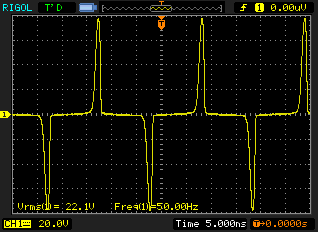
Figure 1.3 - Current Transformer Saturation
This is what happens with 10A primary current but with no burden. Although the test transformer is rated for 5A, it performs perfectly at double the rated current with the 100 ohm burden in place. Without the burden things are very different! As you can see, the output waveform is highly distorted due to heavy core saturation. Re-connecting the 100 ohm burden instantly restored the normal voltage and waveform, in this case a clean sinewave at 1V RMS.
Without the burden, the core is pushed into hard saturation and the secondary voltage rises significantly (and alarmingly). At 50Hz and 10A, the output voltage is very distorted, and reached 80V peak and 22V RMS. With 10A (but at an increased frequency to avoid saturation) I was able to measure 200V RMS at the secondary. This also reverted to the expected 1V RMS as soon as the 100 ohm burden was re-connected. Imagine what might happen to you if the transformer had a 5A secondary and was monitoring 10,000A instead of only 10A, and the burden was disconnected. Yes, the impedance is high, but with 5A output current available it's extremely dangerous - and the very high voltage can also damage the insulation on the secondary winding.
There are some pretty bizarre 'explanations' on the Net as to why the voltage rises when the load (burden) is removed. The simple (and easiest to understand) is that as noted, it is a current transformer. The secondary's output is defined as a current, not a voltage. A current source (and that's what a CT really is) will always try to force the expected current to flow in its load (the burden) regardless of impedance. Naturally, this can only occur within the limitations of the device itself, but it is this very property that causes the voltage to rise. If the burden is removed, an ideal current source would have an infinite voltage, since it is attempting to force current into an open circuit. In reality, normal losses (core loss, core saturation, leakage inductance, finite insulation resistance etc.) will limit the final voltage, but in some cases not before the insulation fails and the transformer is ruined and/or the electrician's family is a member short.
Compare this with a voltage transformer, which will try to maintain the designed output voltage regardless of how much current is drawn. Again, losses mean that a short circuit (the voltage transformer's equivalent of a current transformer's open circuit) will not cause infinite current to flow. The end result will be the same for both though - a broken transformer. It's easy to protect both - a fuse for the voltage transformer and something to limit the output voltage to a safe value for the current transformer (discussed below).
As has been shown in the measured data, when the burden is removed there is a dramatic increase of the primary inductance, which means that the voltage across the (most commonly) single turn primary will increase proportionally. More voltage across the primary means more voltage across the secondary - this relationship is immediately obvious. A simulation proved this quite convincingly, and matched my measured results very closely. Now you know the real reason the voltage increases - perfectly simple and makes complete sense ... but it's still a current source.
To prevent CT failure, just add a safety voltage clamp such as a MOV (metal-oxide varistor) or a couple of zener diodes (wired in series, back-to-back) in parallel with the secondary winding. This is cheap and effective safety measure for small CTs with low output current. At the low voltage normally expected from the CT, the safety clamp will be inactive and will not influence the reading. For a large CT operating with a 5A output current (for example) a somewhat more robust solution is called for, but the principle is not hard and is a lot cheaper (and kinder) than replacing a failed transformer or electrician.
Something that you rarely see mentioned is both interesting and useful, and is touched upon above. If a current transformer is rated at 5A (like the one I used for my tests), you can get improved accuracy at low currents by winding more turns through the core. If you were to make the primary winding 10 turns instead of the normal single turn, you'll get the full 5mA rated secondary current with only 500mA in the primary. We expect that when turns are added to the primary, the voltage is reduced - in this respect a current transformer appears to defy the normal rules that apply to transformers. I hasten to reassure the reader that no rules are broken, and the laws of physics as we know them are still firmly in place. (Manufacturers know about this and may provide extensive help for the user, but most articles on the Net don't mention it.)
Remember ampere-turns mentioned earlier? There's the clue to what happens - multiply the current in Amps by the number of turns. If 1A flows through 1 turn, that's 1 ampere-turn. If we have 10 turns and 100mA, that's also 1 ampere-turn. On the secondary side (1000:1 tranny) we have 1,000 turns at 1mA - still 1 ampere-turn. The same concept applies regardless of the turns ratio or primary/ secondary current.
One thing must be made perfectly clear - the current used in the measuring circuit attached to the secondary is not free energy  . If we have a primary voltage of 230V, a load current of 10A and a secondary current of 10mA into a total resistance of 100 ohms (1V), the voltage to the load is actually 229.999V (1mV difference, ignoring losses). The load power is reduced by 10mW. This is easily determined ...
P = V × I
P = 1mV × 10A = 10mW (primary side - transferred to the secondary)
P = 1V × 10mA = 10mW (secondary - this power is dissipated in the burden and winding resistance)
The loss of 10mW is verging on insignificant, but it is important to understand that there are losses, and like all losses they accumulate. Adding a current transformer to a circuit is unlikely to cause a measurable loss in reality, because normal cable resistance in the power circuits will cause losses that are orders of magnitude greater.
Predictably, you won't find any 1A CTs with a 5A output - the output from a current transformer is always expected to be a very small fraction of the load current.
During my tests, I found that the high frequency limit was much greater than that of the amplifier I used to test the tranny - there was no evidence of HF rolloff, even at 20kHz. When the correct burden resistor is used, most small current transformers' bandwidth will usually far greater than necessary for most normal current measurements.
However, be aware that high current CTs using a laminated steel core will have much narrower bandwidth, which may only extend to a few hundred Hertz. Iron losses increase dramatically with increasing frequency and cause considerable HF loss. Some current transformers use a small bobbin around part of a split laminated steel core (commonly found in clamp meters), and these have very poor HF performance. It's also worth noting that there are now isolated current sensing ICs (using Hall effect sensors) that replace many traditional CT applications on PCBs. However, the CT has been with us for over 100 years, and it's unlikely that anything will replace completely it for a very long time.
The Hall-effect current monitoring devices as complete ICs are useful and interesting, but noise performance in particular is woeful compared to a current transformer. A Hall-effect device that can handle 10A will be all but useless at 50mA due to noise, and at a current only marginally higher than the rated value, the unit will become highly non-linear. By way of comparison, the 5A current transformer I used for these tests can handle 10 times the rated current (50A) with very little non-linearity!
For anyone who needs to monitor current during servicing or design work, have a look at Project 139. This uses a Hall effect sensor rather than a current transformer. This type of transducer has a wider range, better high frequency response, and are more flexible than current transformers. They also work with DC which can be an advantage. For those who don't need the enhanced bandwidth or gain, see Project 139a - a simplified version of the current monitor that uses a miniature 1000:1 current transformer (same as the one that was used for the tests described here).
It's worth noting that you can use an opamp as a current-to-voltage converter (aka transimpedance amplifier). However, there is rarely any need to do so because the recommended burden resistor will provide more than acceptable accuracy for anything other than extreme precision measurements. However, an opamp I/V converter is described next, even though it is unnecessary in 99% of normal applications. It may also require great care to ensure that the circuit is stable, does not create any DC offset, etc.
Figure 1.4 - Current Transformer With 1mA/ V Current to Voltage Converter
One of the problems you may have with an opamp I/V converter is a very low feedback resistance. This is hard for the opamp to drive properly, although if you use a value of around 1k most opamps will be alright at low output levels. This makes it easy to measure low current if that's what you need to do, and also presents close to zero ohms to the CT's secondary. Fig. 4 shows a more-or-less typical converter, which has a conversion of 1V/ mA, set by R1. Even 1k is bit too low for most opamps, although an NE5324 can handle that easily. Lower gain gets harder because the feedback resistor has to be reduced.
The technique is very useful if you need to measure very low current. If R1 is 10k, the output is 10V/ mA, so you can measure down to a few milliamps with good accuracy. If you were to wind 10 turns for the primary, the conversion is now 100V/ mA, so just 10mA primary current will provide an output of 1V RMS. Note that you will need to include C1 and R2, because there will be a fairly high DC offset. With a 10k resistor for R1, the DC gain of the circuit is 250, which will be troublesome with most opamps.
Use of 1n I/V converter is generally limited to applications where you need to increase the sensitivity of a CT. To reduce the sensitivity it's far easier to reduce the burden resistance. By knowing both techniques you increase the scope of your designs, and get a far lower noise level than can be obtained from Hall effect current sensors or a conventional burden followed by amplification. You also benefit from the (close to) zero input impedance of a transimpedance amplifier. Of course, the CT only works with AC.
A variation on the 'traditional' current transformer is the Rogowski coil, named after its inventor (Walter Rogowski). This coil does not use a core, and is deliberately made in such a way as to allow a gap in the winding so it can be placed around a current-carrying conductor without having to break the circuit. As shown below, the 'other' end of the winding runs through the centre of the turns, so the two ends of the winding are available at one end of the coil. The physical construction varies widely, with typical coils rated from 30A up to 6,000A or more. Most use some kind of 'joiner' to ensure that the two ends are aligned the same way with each usage. This reduces measurement errors.
Figure 2.1 - Rogowski coil
It appears common to use a thicker wire or a flexible tube through the centre, and that creates a handy 'former' for the windings. If the centre winding is made from a suitable (non-magnetic) material, it's easily bent around the conductor to be measured. The output of a Rogowski coil is dependent on the rate of change of load current, and an integrator is required to obtain an output that matches the original load current waveform. It's unlikely that many readers will have a use for Rogowski coils, but if you do, there's a great deal of information on the net. Consequently, I do not intend to go into much further detail.
Sensitivity is somewhat lower than traditional current transformers, although it's easily amplified. Unlike a 'normal' current transformer, there is no high voltage generated if the coil is open-circuit, but it's also important to position a Rogowski coil properly (ideally so the current-carrying conductor is centred through the coil). With many, the error is small, but not all behave the same way. Linearity is very good, because there is no magnetic core to saturate at high currents.
An unexpected use for a current transformer is a 'core balance relay', aka residual current detector or earth leakage circuit breaker. These are safety devices, designed to verify that the current flowing in the active and neutral conductors is the same. Should they differ, that could mean that something (or someone!) is passing current to earth (ground) due to a fault in the appliance. Operation is simple, with both active and neutral conductors both passing through the hole in the middle of the CT.
If the current in each is identical, there is no output from the CT because the magnetic fields are equal and opposite and therefore cancel. If there's leakage to protective earth (or anything else) the current becomes unbalanced, an output is produced from the secondary of the CT, and appropriate circuitry is tripped disconnecting the mains. Safety switches are part and parcel of most electrical installations these days, and they have undoubtedly saved many lives. Perhaps surprisingly, many have no electronics at all, and are purely electromechanical.
Figure 3.1 - Residual Current Detector
Fig 3.1 shows the essential parts, being the current transformer (sense coil) and the sensitive trip coil. These are also covered in the article Current Monitors (Section 5), along with a detailed explanation of how they work. Most 'standard' RCDs are designed to trip with a (maximum) 30mA imbalance, so the trip coil needs to be very sensitive, because the output from the CT will be much less than that. The contacts are held closed when the breaker is on, and the trip coil causes the release mechanism to trigger, opening the contacts. Rfault could be an insulation failure or a person making contact with a live circuit.
Most RCDs also include a standard thermal/ magnetic circuit breaker as well, so the circuit is protected against overloads or short circuits. When an imbalance is detected, the RCD should trip within 300ms. The 'TEST' button connects an internal resistor that is designed to pass 30mA at the rated voltage (230V in Australia, so 7.7kΩ). More sensitive versions are required for medical applications where a person/ patient is directly connected to electrical equipment (which must be rated as 'medical grade').
It's notable that 'simple' RCDs such as that depicted above are no longer permitted in Australia (and likely elsewhere as well). This is a Type-AC RCD, which detects only AC leakage. All RCDs are now expected to be Type-A (AC plus pulsating DC), Type-F (AC, pulsating DC or high-frequency AC) or Type-B (AC, high-frequency AC, pulsed DC and smoothed DC), with the latter types designed for electric vehicle chargers. The most common 'general purpose' RCD is now the Type-A.
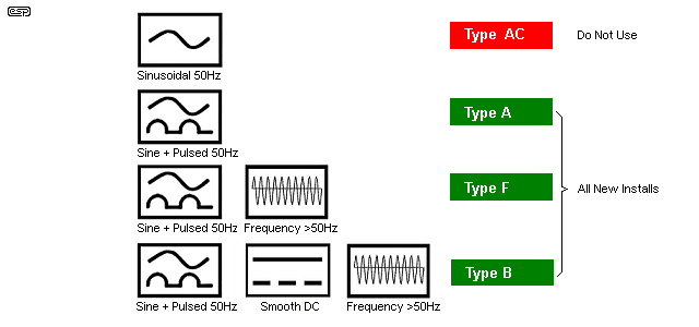
Figure 3.2 - Symbols For RCD Types
The minimum requirement in most jurisdictions is now a Type-A. Unlike basic Type-AC versions, there will almost certainly be some electronics involved to achieve anything more advanced than Type-AC. The electronics are not described here, as detailed and accurate information is difficult to find.
It's worthwhile to understand that any toroidal transformer can be used as a current transformer. Simply pass the current-carrying wire through the centre, and voila! A current transformer is created. While this definitely works (yes, I've tried it), determining the optimum burden resistance may be tiresome, and unless you perform a measurement to determine the turns ratio and work out the number of primary turns, calibration will be uncertain. In addition, toroidal transformers (even small ones) are larger and much more expensive than a typical dedicated current transformer, but it's still a trick you can use if you need to measure high current and don't have a suitable current transformer handy.
This will hopefully clear up some of the misconceptions that seem to abound. There is nothing difficult, just a different way of looking at a familiar component. Most people will never use a current transformer, and many won't even have known that such a device existed until they read this article.
This is a brief introduction to current transformers. The topic is vast, as is the range of CTs that are in use, so it's only possible to cover the basics. If you follow the guidelines given here you'll have a working current transformer set up in no time, and you can play with the burden and experiment to your heart's content. Experimentation is ultimately the only way that you'll really learn any topic in electronics, and you'll find that there are a surprising number of applications where a CT is either useful or essential.
CTs are also used for protection circuits. If you have a 1,000A mains feeder, a short circuit will obviously do considerable damage. Attempting to monitor that current with an overgrown circuit breaker would be non-sensible, so a CT is used for monitoring, and that feeds the trip mechanism of the main circuit breaker. This will pretty obviously be a somewhat large device, rated to break well in excess of 1,000A at whatever voltage is being used. In most cases now, the trip characteristics will probably be determined electronically, because an electronic circuit can be tailored for the response required far more easily than a mechanical circuit.
Transformer Articles ...Use these links for the other sections of this series.
Countless different books and Web pages were researched during the compilation of this article, and although some were interesting, the majority were of minimal use. Of those who I actually remember (a daunting task in itself, considering the sheer amount of searching I had to do), there's a complete list in the Transformers - Part 2 article. The link takes you directly to the references section.
| Main Index
Articles Index
|