
|
|
| Elliott Sound Products | Project 84 |
 Main Index
Projects Index Main Index
Projects Index
|
 Please Note: PCBs are available for this project. Click the PCB image on the left for the pricelist.
Your sub is installed and set up as best you can, but you can't quite get it to sound right. Some frequencies are too prominent, while others seem subdued. If this sounds familiar, then this equaliser is what you need to fix it. It is not a panacea, and will not cure an impossible room, but the majority of lumps and bumps in the subwoofer response will respond very well to an equaliser as described here.
The unit is an 8 band variation on the expandable equaliser described in the Project Pages, and is dedicated to its task. Boards can be stacked to get more bands if desired, but the arrangement shown will be quite sufficient for most installations.
The equaliser is a constant Q design, so unlike most 'ordinary' equalisers, it does not have a very low Q at low settings of boost and cut. This is a major problem with the standard (graphic) equaliser circuit, and is completely avoided by the constant Q version. Using the Multiple Feedback Bandpass design, these filters can be designed for any (reasonable) frequency and Q desired. As a 1/3 Octave equaliser, the filter Q should be 4.3, but I have deliberately lowered this to 4 for this design to allow a little overlap.
While there will always be 'that' room which defies all attempts to make anything sound halfway decent, this EQ will dispose of the majority of problems likely to be encountered.
The equaliser is 1/3 Octave band, with centre frequencies at 25, 32, 40, 50, 63, 80, 100 and 125 Hz. It can also be used with a starting frequency of 16 or 20Hz if desired (see table below). The circuit itself uses an opamp as an input buffer (U1A), ensuring a low impedance drive to the following inverting buffer. All filters are driven by an inverted signal from U2B, and the maximum amount of boost or cut is determined by the value of R8.
U1B is a summing amp, and it takes its input from the combination of the input, and the output signal from the 'CUT' bus - this comes from the pots used as the level control for each frequency band. The combined signal is summed again by U2A, this time with the signal from the BOOST ('BST') bus added. The signal drive to all filters is performed by U2B, the gain of which determines the maximum boost and cut allowed. As shown, The circuit will provide about ±14dB, and the response is completely flat with all pots centred. Reduce the range by reducing the value of R8 (39k) - a value of 10k gives 6dB of boost and cut.
The actual operation of the circuit relies primarily on the amplitude and phase of the selected frequency, and it is beyond the scope of this article to cover it in great detail. The inverted signal drive is compensation for the fact that a standard multiple feedback filter is inverting at the resonant frequency - I shall leave it to the reader to work out exactly what happens (assuming you care, of course). For full details of the circuit topology, see the reference below.
Although not shown here, there is a bypass cap for each dual opamp. These should be 100nF multilayer ceramic types for best performance. This is critical if high speed opamps are used, but still important if using the recommended TL072 opamps. There is little or nothing to be gained in using 'audiophile' grade opamps for a subwoofer, since the TL072 has more than sufficient bandwidth for the job. Naturally if it makes you feel better, then NE5532, OPA2134 or similar opamps work beautifully.
 |
The figure on the left (top view) shows the standard pinouts used for the vast majority or basically all dual opamps. If the PCB is used for this project (highly recommended, by the way), then only opamps with this pin configuration may be used. This is not a limitation.  Correct insertion is (as always) essential, or the opamps will die ! Correct insertion is (as always) essential, or the opamps will die ! |
The filters are repeated - two (the first and last) are shown in Figure 2, and a multiple feedback (MFB) filter block is used 8 times to get the eight bands.
The table below shows the designations for all the filter sections. The output caps (10µF 63V as shown) may also be bipolar electrolytics - film caps would be nice, but are simply too large to fit on a decent sized board. The difference in performance is unlikely to be audible with any system, since the caps are very much bigger than they need to be at even the lowest frequency. The -3dB frequency for all output networks in this section is 1.6Hz worst case - well below anything we can hear.
The frequency selection components are shown in the following table - these are quite accurate, and will generally be suitable for all applications. I have included the 16Hz band for those who may want to move the range down slightly - only eight of the frequencies are used for the unit. The nomenclature for the various MFB filter components has been changed to match the markings on the PCB - this makes component placement a lot easier. In general, the range from 25Hz to 125Hz will be more than sufficient for all but the most potent subs. There are 10 different frequencies listed in the table, so just choose 8 contiguous filters from those shown (e.g. from 20Hz to 100Hz, or 16Hz to 80Hz).
| Freq Band | Ri | Re | Rf | Ci, Cf |
| 16 | 330k | 10k | 680k | 120nF |
| 20 | 330k | 10k | 680k | 100nF |
| 25 | 270k | 8k2 | 510k | 100nF |
| 31 | 270k | 8k2 | 510k | 82nF |
| 40 | 330k | 10k | 680k | 47nF |
| 50 | 330k | 10k | 680k | 39nF |
| 63 | 270k | 8k2 | 510k | 39nF |
| 80 | 82k | 2k7 | 160k | 100nF |
| 100 | 82k | 2k7 | 160k | 82nF |
| 125 | 150k | 4k7 | 330k | 33nF |
Arrrgh! The values are all over the place - this was done to avoid having to use caps in parallel (there is no room on the board), and I have tried to maintain at least passably sensible values. Unfortunately, maintaining the Q and frequency for such closely spaced filters is not easy, and the table above is the result. Feel free to use the MFB Filter calculator program to see if you can do any better - it is available from the Download page. Alternatively, have a look at Project 63 (Multiple Feedback Bandpass Filters) which are the basis of this project and the formulae you need are shown. They can be loaded into a spreadsheet for ease of calculation, and you can experiment to your heart's content.
Finally, the DC power supply section. This allows the P84 board to be run as a stand-alone unit, requiring only an AC power input. While the P05 Power Supply is recommended for this unit, in many cases it will be easier to use the on-board supply. Because of size constraints, the main filter caps are the smallest value that will work, so the supply is only capable of relatively low current (I suggest about 100mA maximum). This is sufficient to run the equaliser, but probably not along with a P48 or P71 circuit for speaker correction. The AC section is completely optional - it can be omitted (delete the two diodes, C2, C3, C6-C9, U7 and U8). ±15V is then connected to the DC input from an external supply. Depending on your supplier, it may be possible to fit larger caps than shown - I used 2,200μF 25V electros on the prototype, and they just fit (12.7mm diameter).
There is one bypass cap for each opamp. While most commonly used devices don't need this level of bypassing, it doesn't hurt and allows 'better' opamps to be used if it makes you feel better. In most cases, the suggested TL072 opamps are more than good enough for the application and any upgrade is unlikely to be audible. Be aware that most high performance opamps draw a comparatively high current (up to 16mA per package for the NE5532), so only use the on-board supply if low current opamps are used. The TL072 draws a typical current of 2.8mA per package (5mA maximum).
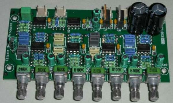
 | The PCB for this project is designed to use miniature (9mm square, with or without PCB mounting frame) rotary pots, so the term 'graphic' equaliser is something of a misnomer. If desired, slide pots may be used, but will have to be wired to the board. This is not as arduous as may first be thought, as there are only 10 wires needed for the 8 pots. |
The prototype unit pictured above was measured, using 15V AC input and no housing (or shielding) of any kind. Noise was measured at less than 1mV unweighted (3Hz-300kHz bandwidth). The DC offset of the prototype was 8mV at the output, so you need a coupling cap for the subwoofer amp.
With a 15V AC supply, total AC current draw was 92mA. This will be higher if you use opamps that draw more quiescent current, but even worst case will typically be less than 250mA. Unregulated ripple voltage was 65mV RMS with the 2,200uF filter caps installed. If you use smaller caps, it will be higher. Note that ripple is 50Hz (or 60Hz), and not 100/120Hz as you might expect. This is because the power supply is a simple voltage doubler for maximum flexibility.
The absolute maximum input or output voltage is just under 10V RMS. With maximum boost, there is a gain of 14dB (5 times), so a 1V signal becomes 5V (which will clip any known power amplifier). In general, it is advisable to use a level control between the P84 output and the amplifier input so that the system becomes more controllable. The input level must be kept below 2V RMS at all times if maximum boost is being applied at any frequency.
Maximum boost (or cut) is unlikely for most installations, and should be avoided if at all possible. The need for such aggressive equalisation indicates that there are other problems that should be addressed. It may be necessary to change the location of the sub, use a pair of subs in different places in the room, or apply room treatment.
Connect the equaliser into the signal path (usually between the source and the subwoofer equalisation and/or power amplifier). Make sure that all pots are centred for an initial flat response. Verify that the sub sounds the same as before, then preferably with a test CD (known music will work too, but is not as predictable), run a frequency sweep (or burst signals) and adjust the equaliser for the smoothest response in the low frequencies. You should be in your normal listening position for this - the sound quality will be different in different parts of the room, and this is part of the problem in the first place.
Make adjustments sparingly - over use of an equaliser is a guaranteed way to ruin the sound, so make adjustments in small increments, one band at a time. It may take a while before you are completely happy, but careful listening and perseverance are the key to getting it right. Generally, you are more likely to need a reasonable amount of cut than boost, and although possible, it is not really practical to make the circuit asymmetrical.
Once set, the EQ settings will not need to be changed, so the unit should be placed where it is not readily accessible - you know what will happen if others know that it's there, and what it does.
The settings will need to be changed if the subwoofer is moved, or if furniture is moved, added or removed from the listening area. Large soft furnishings will make the biggest difference, while small (open) shelves will usually make little or no change at all. Book cases are highly unpredictable animals, and only careful evaluation will determine if the settings remain accurate if a bookcase is added or removed.
The design presented here is based on a paper (Constant Q Graphic Equalisers), written by Dennis A. Bohn of Rane Corporation. The original work (constanq.pdf) was once available from the Rane site, but alas it is no more. Constant-Q Graphic Equalizers is available, and while it has some useful info, much of the original is not included.
| Main Index
Projects Index
|